Wiring of the standard device
Wiring of the feedback system
Incremental encoder with TTL level at X8
5
5.8
5.8.2
5.8−2
EDSVF9383V EN 7.1−04/2012
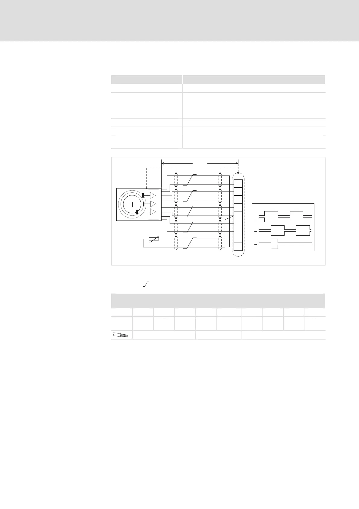
5.8.2 Incremental encoder with TTL level at X8
Field Values
Connection at drive controller Connector: Pin, 9−pole, Sub−D
Connectable incremental
encoder
Incremental encoder with TTL level
l Encoder with two 5V complementary signals electrically
offset by 90°
l Connection of zero track is possible (optional)
Input frequency 0 ... 500 kHz
Current consumption 6 mA per channel
Internal voltage source
(X8/4, X8/5)
5 V DC / max. 200 mA
B
V
CC
GND
Z
+KTY
-KTY
1
2
3
4
5
6
7
8
9
A
X8
<50m
A
A
A
B
Z
B
B
Z
Z
KTY
9300VEC018
Fig. 5.8−1 Connection of incremental encoder with TTL level (RS−422)
Signals for CW rotation
Cores twisted in pairs
X8 − Incremental encoder with TTL level
Connector: Pin, 9−pole, Sub−D
Pin 1
2 3 4 5 6 7 8 9
Signal B A A V
CC
GND
(−KTY)
Z Z +KTY B
0.14 mm
2
(AWG 26) 1 mm
2
(AWG 18) 0.14 mm
2
(AWG 26)
Technical data
Wiring

 Loading...


