Control terminals
Important notes
5.6
5.6.1
5.6−1
EDSVF9383V EN 7.1−04/2012
5.6 Control terminals
5.6.1 Important notes
Stop!
The control card will be damaged if
ƒ the voltage between X5/39 and PE or X6/7 and PE is greater
than 50 V,
ƒ the voltage between voltage source and X6/7 exceeds 10 V
(common mode) in case of supply via external voltage source.
Limit the voltage before switching on the drive controller:
ƒ Connect X5/39, X6/2, X6/4 and X6/7 directly to PE or
ƒ use voltage−limiting components.
ƒ For trouble−free operation, the control cables must be shielded:
– Connect the shield of digital input and output cables at both ends.
– Connect the shield of analog input and output cables at one end (at
the drive controller).
– For lengths of 200 mm and more, use only shielded cables for analog
and digital inputs and outputs. Under 200 mm, unshielded but
twisted cables may be used.
3
10
2
9300vec063
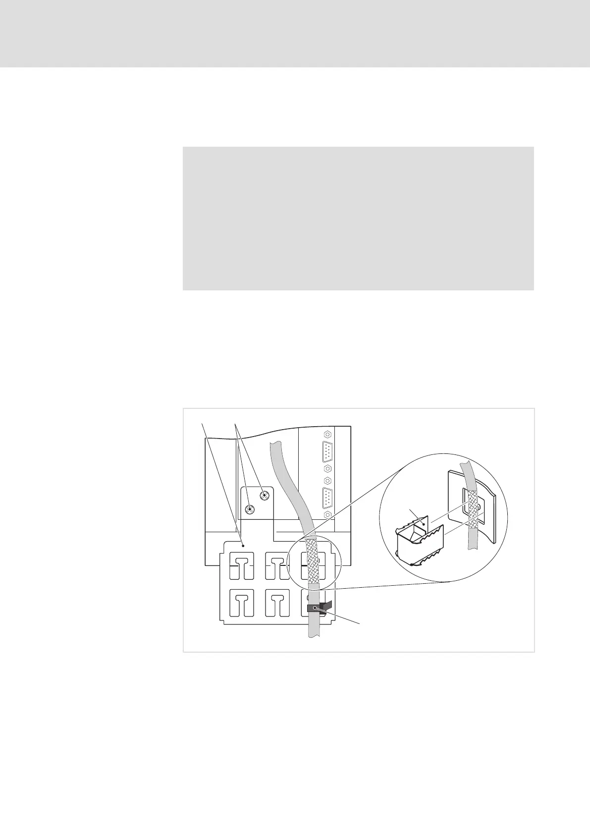
Fig. 5.6−1 Connection of the cable shield with shield clip and strain relief with cable binder
Shield sheet
Fasten shield sheet with two screws M4 × 12 mm at the bottom of the
control card
Connect cable shield with shield clip to the shield sheet
Provide a strain relief of the control cable at the shield sheet by means of a
cable binder
How to connect the shield

 Loading...


