Control terminals
Terminal assignment
5.6
5.6.5
5.6−9
EDSVF9383V EN 7.1−04/2012
5.6.5 Terminal assignment
Terminal
Function
Bold print = Lenze setting
Level / state Technical data
X11/K32
X11/K31
Safety relay K
SR
1st
disconnecting
path
Feedback − pulse inhibit
Open contact: Pulse inhibit is
inactive (operation)
See chapter "Technical
data"
Closed contact: Pulse inhibit is
active
X11/33 – coil of safety relay K
SR
Coil is not carrying any
current: Active pulse inhibit
X11/34 + coil of safety relay K
SR
Coil is carrying current:
Inactive pulse inhibit
(operation)
X5/28 Controller inhibit
(DCTRL−CINH)
2nd
disconnecting
path
Controller enable/inhibit LOW: Controller inhibited
HIGH: Controller enabled
LOW: 0 ... +3 V
HIGH: +12 ... +30 V
Input current at +24 V:
8 mA per input
Reading and processing
the input signals − 1/ms
(mean value)
X5/E1
Digital inputs
(freely
assignable)
Deactivate CW rotation / quick stop HIGH
X5/E2 Deactivate CCW rotation / quick stop HIGH
X5/E3 Activate fixed frequency 1 (JOG1) HIGH
X5/E4 Set error message (TRIP SET) LOW
X5/E5 Reset error message (TRIP RESET) LOW−HIGH edge
X5/ST1
X5/ST2
Additional digital input (E6) HIGH
X5/A1
Digital outputs
(freely
assignable)
Error message present LOW
LOW: 0 ... +3 V
HIGH: +12 ... +30 V
Load capacity:
Max. 50 mA per output
(load resistance at least
480
W at +24 V)
Update of the output
signals − 1/ms
X5/A2 Switching threshold Q
MIN
:
Actual speed < setpoint speed in C0017
LOW
X5/A3 Ready for operation (DCTRL−RDY) HIGH
X5/A4 Maximum current reached
(DCTRL−IMAX)
HIGH
X5/39 – GND2, reference potential for digital
signals
– Isolated against GND1
X5/59 – Connection of external voltage source
for backup operation of the drive
controller in case of mains failure
DC 24 V (+18 ... +30 V) Current consumption:
Max. 1 A at 24 V
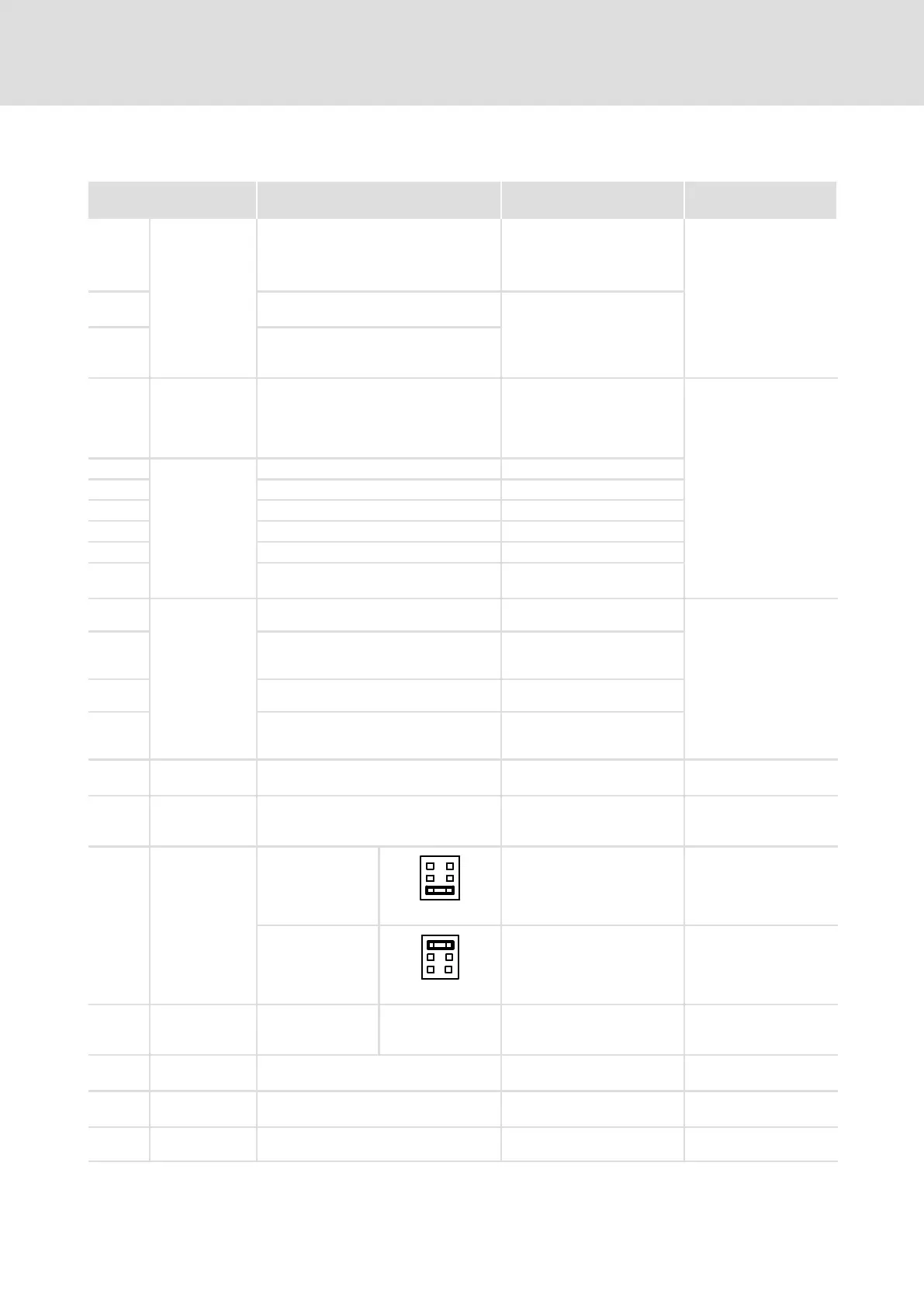
X6/1
X6/2
Analog input 1 Voltage input
range
Main setpoint
6
4
2
5
3
1
−10 V ... +10 V Resolution:
5 mV (11 bits + sign)
Jumper X3
Current input
range
6
4
2
5
3
1
−20 mA ... +20 mA Resolution: 20 mA
(10 bits + sign)
Jumper X3
X6/3
X6/4
Analog input 2 Voltage input
range
Not active
Jumper X3 has no
effect
−10 V ... +10 V Resolution: 5 mV
(11 bits + sign)
X6/62 Analog output 1 Monitor 1
Actual speed value
−10 V ... +10 V
max. 2 mA
Resolution: 20 mV
(9 bits + sign)
X6/63 Analog output 2 Monitor 2
Actual motor current value
−10 V ... +10 V
max. 2 mA
Resolution: 20 mV
(9 bits + sign)
X6/7 – GND1, reference potential for analog
signals
– –

 Loading...


