Technical data
Rated data (devices in 400V design)
3
3.5
3.5−1
EDSVF9383V EN 4.0−11/2007
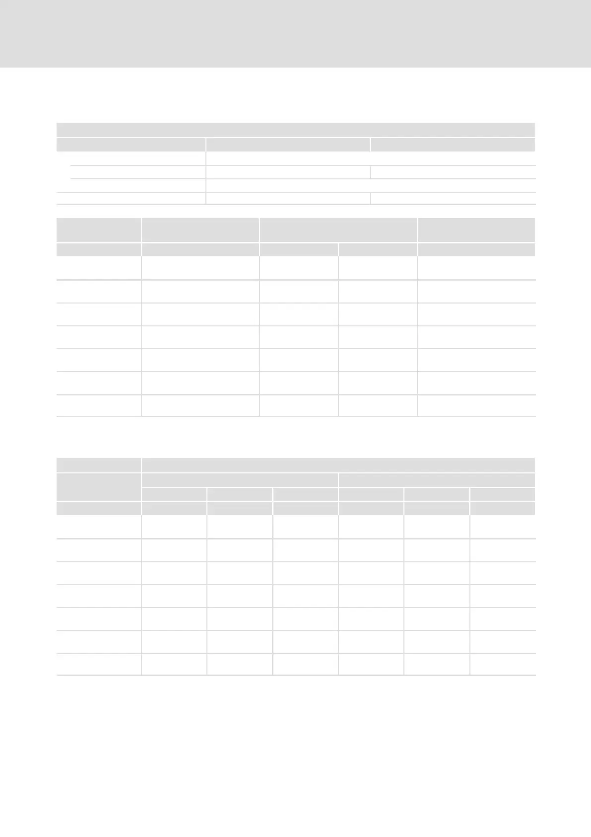
3.5 Rated data (devices in 400V design)
Basis of the data
Voltage Frequency
Supply
3/PE AC 400 V [U
N
] 340 V − 0 % ... 456 V + 0 % 45 Hz − 0 % ... 65 Hz + 0 %
DC (alternatively) [U
DC
] Not possible
Output voltage [U
OUT
] 3 ~ 0 ... U
N
0 ... 300 Hz
9300 Mains current
1)
Typical motor power
ASM (4−pole)
Power loss
Type I
r
[A] P
N
[kW] P
N
[hp] P
V
[kW]
EVF9335−EV
EVF9335−EVVxxx
2)
200 110
150 2.8
EVF9336−EV
EVF9336−EVVxxx
2)
238 132 200 3.3
EVF9337−EV
EVF9337−EVVxxx
2)
285 160 250 4.0
EVF9338−EV
EVF9338−EVVxxx
2)
356 200 300 5.0
EVF9381−EV
EVF9381−EVVxxx
2)
475 250 350 6.6
EVF9382−EV
EVF9382−EVVxxx
2)
570 315 450 8.0
EVF9383−EV
EVF9384−EVVxxx
2)
713 400 550 10.0
The currents for EVF9381 ... EVF9383 are to be considered as total currents of master and slave
1)
For a controller switching frequency of 2 kHz
2)
Device in variant V030, V060 or V110
9300 Output currents
Rated current Maximum current
2)
1 kHz
1)
2 kHz
1)
4 kHz
1)
1 kHz
1)
2 kHz
1)
4 kHz
1)
Type I
N1
[A] I
N2
[A] I
N4
[A] I
M1
[A] I
M2
[A] I
M4
[A]
EVF9335−EV
EVF9335−EVVxxx
3)
210 210 210 315 315 315
EVF9336−EV
EVF9336−EVVxxx
3)
250 250 250 375 375 375
EVF9337−EV
EVF9337−EVVxxx
3)
300 300 270 450 450 405
EVF9338−EV
EVF9338−EVVxxx
3)
375 375 330 560 560 495
EVF9381−EV
EVF9381−EVVxxx
3)
500 500 500 750 750 750
EVF9382−EV
EVF9382−EVVxxx
3)
600 600 540 900 900 810
EVF9383−EV
EVF9384−EVVxxx
3)
750 750 660 1125 1125 990
The currents for EVF9381 ... EVF9383 are to be considered as total currents of master and slave
Bold print = Lenze setting
1)
Switching frequency of the inverter
2)
The currents apply to a periodic load change with an overcurrent time of 1 minute at a maximum
and a base load time of 2 minutes with maximally 75 % I
Nx
3)
Device in variant V030, V060 or V110

 Loading...


