Configuration
Monitoring
Heatsink temperature
8
8.3
8.3.8
8.3−7
EDSVF9383V EN 7.1−04/2012
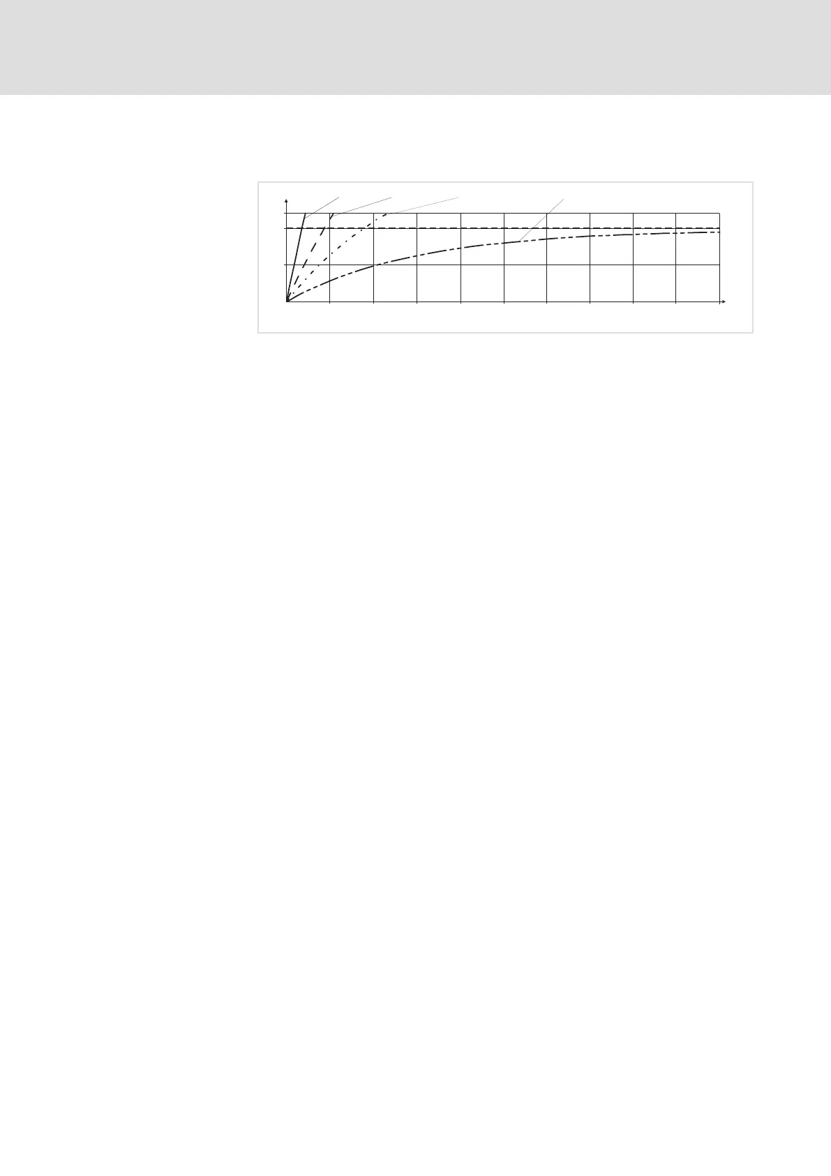
Diagram for the determination of the release times of a motor with a
thermal motor time factor of 5 min:
I =3×I
mot r
0
50
100
120
0 100 200 300 400 500 600 700 800 900
1000
t [s]
I t [%]
2
I=2×I
mot r
I =1.5×I
mot r
I =1×I
mot r
9300std105
Fig. 8.3−2 I
2
× t−monitoring: Release times for different motor currents and trigger
thresholds
Imot Motor current
I
r
Rated motor current
I
2
tI
2
t load
T Time
8.3.8 Heatsink temperature
Via a temperature threshold, the heatsink temperature of the controller can
be monitored:
ƒ Adjustable threshold (OH4) under C0122
– The reset point is 5° C below the adjusted threshold.
ƒ Fixed threshold (OH) = 85° C
– The reset point is at 80° C.
The response for exceeding the adjustable threshold can be set under C0582.
Reading the release time off
the diagram

 Loading...


