Braking operation
Lenze brake resistors
Connection of external brake resistor
12
12.2
12.2.4
12.2−3
EDSVF9383V EN 7.1−04/2012
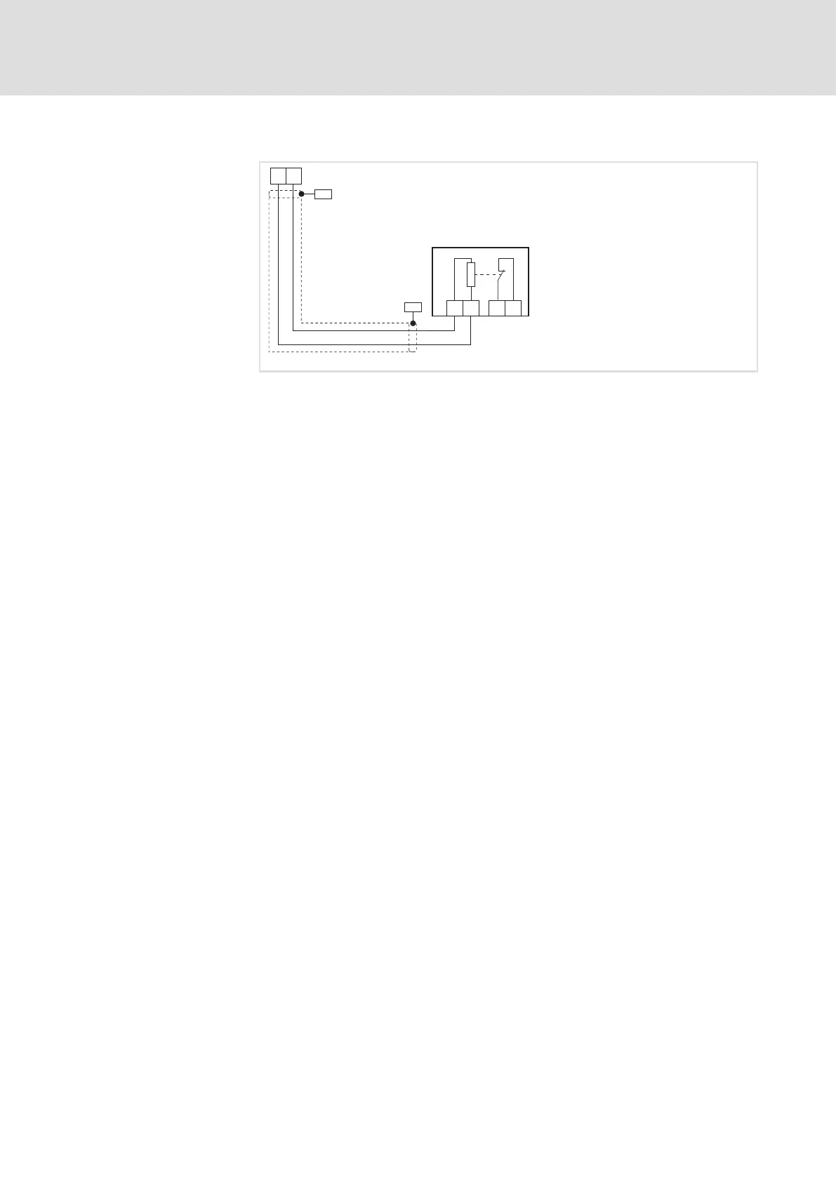
12.2.4 Connection of external brake resistor
PES
BR1 BR2
Z1
PES
J
RB
RB
RB2 T1RB1 T2
9300VEC033
Fig. 12.2−2 Brake resistor connection
RB1, RB2 Controller terminals for connecting the brake resistor
Z1 Brake resistor
PES HF−shield end by PE connection through shield bracket.
ƒ Brake resistors can get hot and under certain conditions a brake
resistor can even burn down. For this reason, the brake resistors must
be mounted so that the possibly high temperatures cannot cause any
damage.
ƒ Provide a safety shutdown in the event the brake resistor overheats.
ƒ Use the thermal contacts of the brake resistor (e.g. T1 / T2) as control
contacts to disconnect the controller from the cable!
ƒ Only use shielded brake resistor cables.
ƒ Connect the shield close to the controller and close to the brake resistor
with a surface as large as possible to the mounting plate by using a
shield clamp.
ƒ The shield of the control cables for digital signals (temperature
monitoring T1 / T2) must be connected at both sides (controller and
brake resistor).
ƒ Unshielded cables between shield clamp and connection terminals
must not be longer than 40 mm.
Important notes

 Loading...


