Basic devices in the power range 250 ... 400 kW
Motor connection
5.5
5.5.8
5.5−12
EDSVF9383V EN 7.1−04/2012
0
1
BR2 BR2BR1 BR1
PE PE
UUVVWW
40 mm 40 mm
PE
15-20 Nm
M6
133-176 lb-in
PE
15-20 Nm
M6
133-176 lb-in
U, V, W
25-30 Nm
M8
221-264 lb-in
U, V, W
25-30 Nm
M8
221-264 lb-in
22
33
max.
300 mm
max.
300 mm
9300VEC036
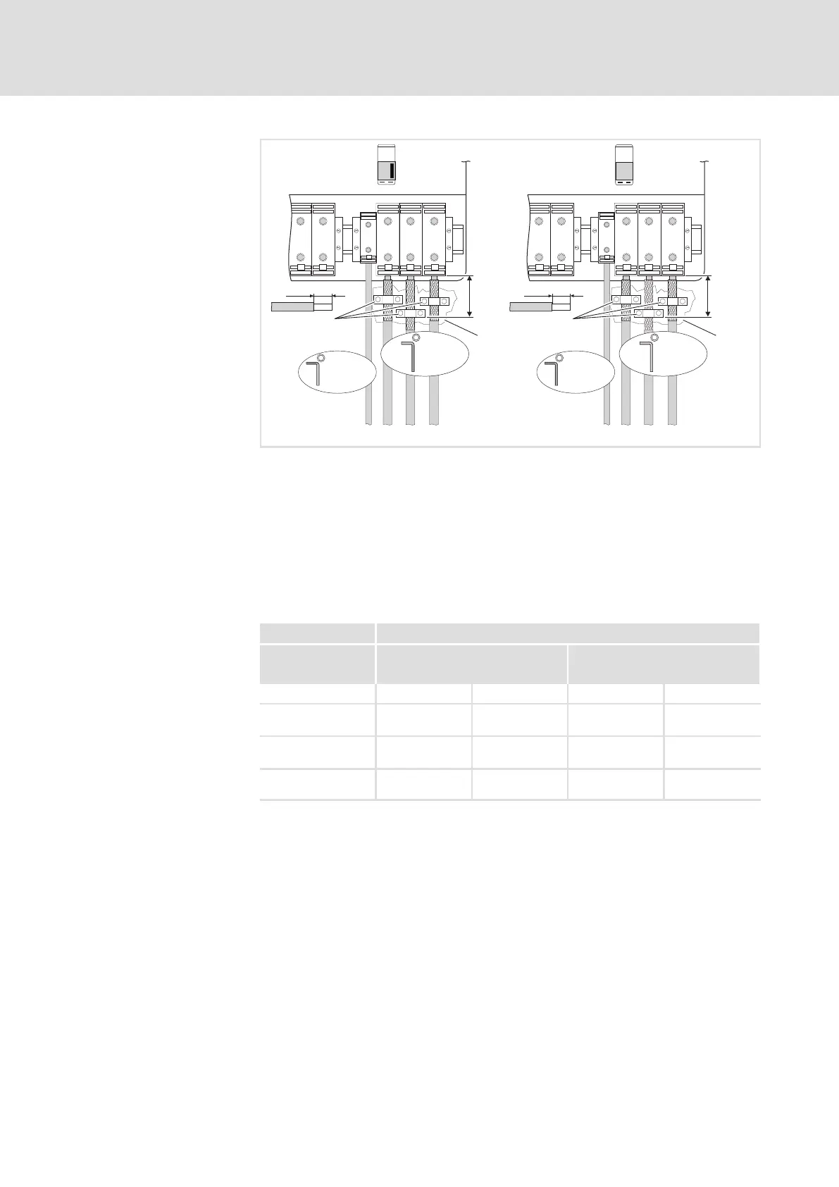
Fig. 5.5−12 Motor connection example
BR1, BR2 Brake resistors can only be operated with variants V060, V110, V270
and V300
Master terminals
Slave terminals
Connect the motor cable shield with a surface as large as possible to
the control cabinet mounting plate by using the clamps.
Conductive surface
Ensure to have the poles right!
Do not exceed the maximum motor cable length!
9300 vector Installation in accordance with EN 60204−1
U, V, W PE
Type [mm
2
] [mm
2
]
Master Slave Master Slave
EVF9381−EV
EVF9381−EVVxxx
150
2 × 50
1)
150
2 × 50
1)
95 95
EVF9382−EV
EVF9382−EVVxxx
150
2 × 50
1)
150
2 × 50
1)
95 95
EVF9383−EV
EVF9383−EVVxxx
240
2 × 95
1)
240
2 × 95
1)
150 150
1)
Two conductors per path; both conductors must have the same
cross−section
Observe the national and regional legislation
Motor connection
Cable cross−section

 Loading...


