5-6 Service Manual
7014-xxx
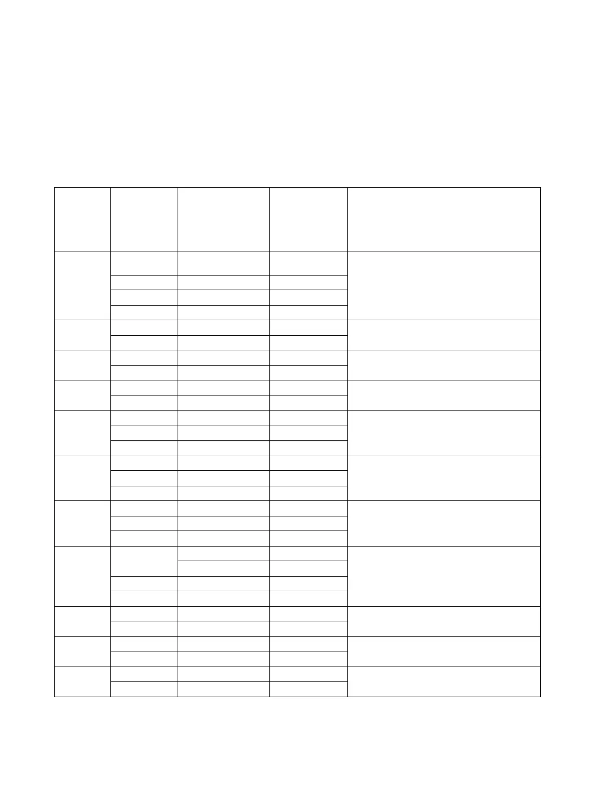
Lexmark X46x controller and engine board connector pin values
Note: The connections listed below are located on the controller board or the engine board. The comments
column lists which board the connection appears on.
Note: See the wiring diagram at back of book.
These values were measured with all connections made (plugged) or with only one connector at a time
unplugged to expose the pins. Always disconnect and connect with the printer power off. Otherwise, the values
below may not match.
Connector Pin # Value
cable plugged
Value
cable unplugged
(if different)
Comments
J8 1, 3, 5, 7, 9,
11, 14
Signals Modem - Controller Board
10 5 V dc
12, 13 3.3 V dc
2, 4, 6, 8 Ground
J16 10, 12, 14 +5V ISP - Controller Board
1, 4 7 Ground
J7 1 +5V Cave light - Controller board
4 Ground
J99 3 +3.3V Controller cooling fan - Controller board
1 Ground
J4 1 Ground Cartridge - Engine Board
(The front access door must be closed.)
21.7 V dc
3, 4 3.3 V dc
J34 1, 3, 5, 6 3.3 V dc Operator panel (UICC) - Controller Board
10, 16 ,17, 18 5.0 V dc
2, 9, 15 Ground
J6 1 > 0 V dc 5 V dc Printhead - Controller Board
2, 3 5 V dc
4, 5, 6, 7 Ground
J11 1 5 V dc (door closed) Cover open - Controller Board
0 V dc (door open)
25 V dc
3 Ground
J9 1, 10 5 V dc LSU - Controller Board
92.9 V dc
J36 1 24 V dc 0 V dc Cooling fan - Engine Board
2 24 V dc
J10 1 24 V dc 24 V dc Duplex solenoid - Engine Board
2 24 V dc 0 V dc

 Loading...