LS SERIES SERVICE MANUAL
ISSUE 4.0 NEXYGEN PLUS 3 DIAGNOSTICS 9
18 Select TENSION in the DIRECTION drop down box.
19 Move the crosshead to apply the first required load noting that the speed can be varied
during the calibration using the keys shown earlier.
20 When the required load is applied, press the F10 key on the computer keyboard to stop
the machine WITH THE LOAD HELD by the motor drive electronics.
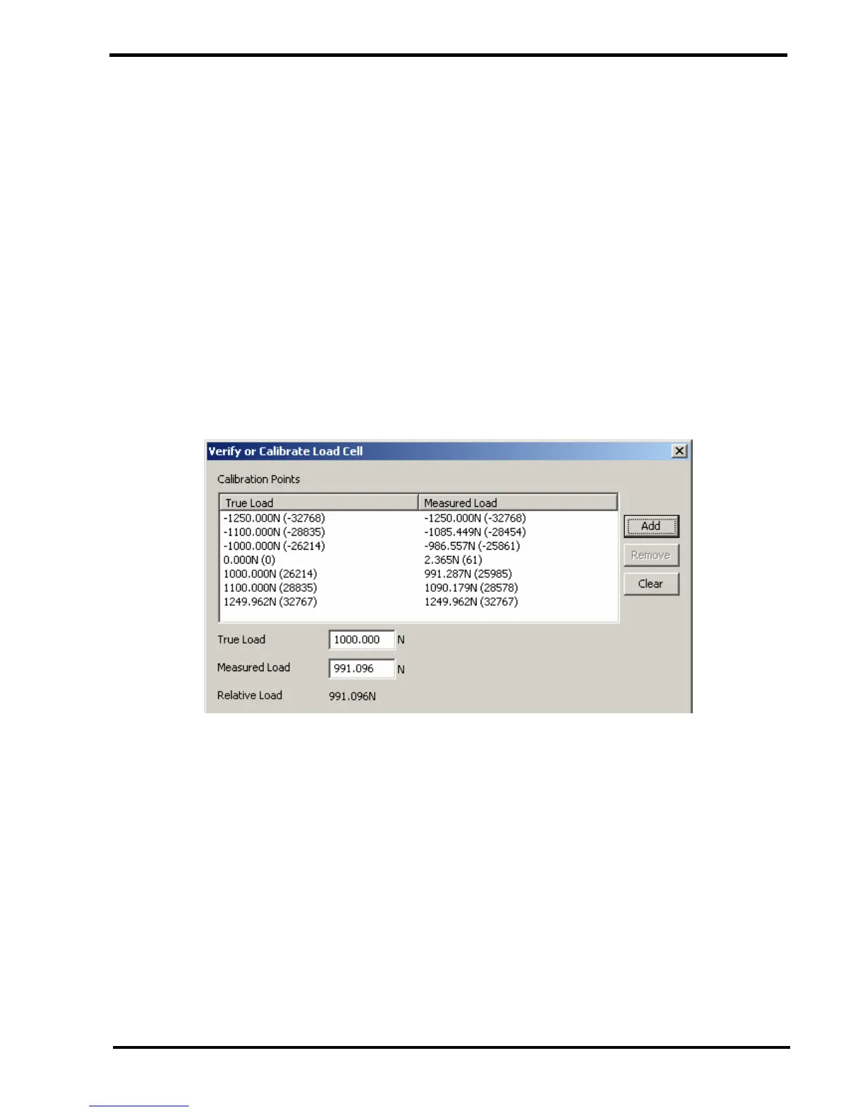
21 Record the load value displayed on the software console into the calibration sheet.
22 If the displayed load reading is NOT within specification, a calibration point will be
required.
23 The value displayed for the True Load will be automatically set to a rounded load value,
e.g. if the console displays a load of 200.04N, the true load will be set to 200.00N.
If the True Load is not showing the required value, manually change the TRUE LOAD
value shown on the software console.
24 Click on the ADD button to the right of the screen to TEMPORARILY add this calibration
point into the system.
Note that a dialog may be displayed requesting if this calibration point is also to be
calculated and stored for COMPRESSION.
25 Press a function key to restart the crosshead in the UP direction and continue the
calibration by applying and recording the required loads up to the full scale value of the
loadcell, entering calibration points as necessary.
26 When the full scale force has been applied, select COMPRESSION in the DIRECTION
drop down box.
27 Move the crosshead to remove all load noting that the speed can be varied during the
calibration using the keys shown earlier.