L-IP User Manual 113 LOYTEC
Version 6.1 LOYTEC electronics GmbH
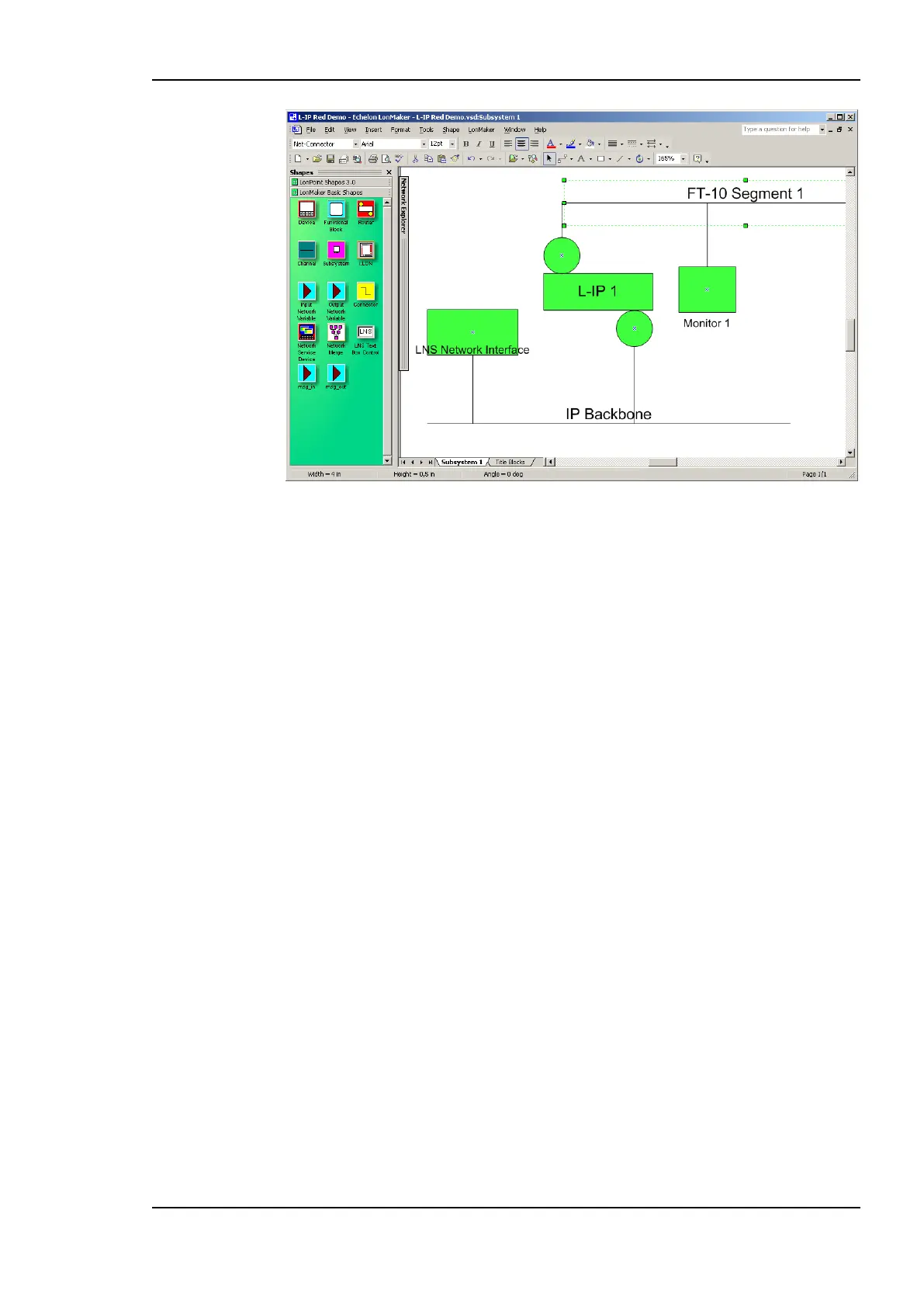
Figure 108: A single L-IP Redundant device configured for standalone operation.
Be sure to commission the router and the diagnostic node. Once they were successfully
commissioned, the PRIM LED on the device should be green.
9.4.3.2 L-IP Redundant with Router Redundancy
For operating the L-IP Redundant in twin router mode (router redundancy, see Figure 99),
the following steps have to be performed:
Add two router shapes. Connect both to the same IP-Channel on one side and to the
same FT-10 Channel on the other side of the router.
Add two L-IP Redundant built-in diagnostic node “L-IP Redundant Diagnostic FT-10”
device shapes on the FT-10 channel. The corresponding device template will be
installed with the L-IP Redundant Plug-In (see Section 9.4.1).
To get a service pin message for commissioning the diagnostic node, press the Status
button on the L-IP Redundant (see Section 4.5) or use the Send Service Pin Msg
button in the corresponding section of the Device Information Page in the Web
interface (see Section 6.1).
Add two “Twin Router” functional blocks, one for each L-IP Redundant diagnostic
node.
Connect nvoRedRtr of one L-IP Redundant with the nviRedRtr of its paired L-IP
Redundant and vice versa.
If using LonMaker for Windows the resulting drawing should look like shown in Figure
109.
 Loading...