CHAPTER 8 - ADVANCED FUNCTIONS
8.1 DC brake
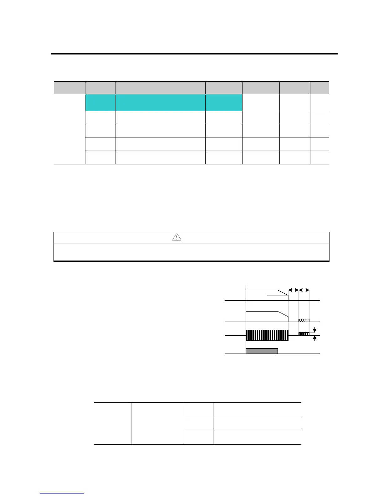
Stopping motor by DC brake
[DC Brake start frequency]
Set F4 - [Stop mode select] to 1.
F 8: The frequency at which the DC brake will become active.
F 9: Inverter output will hold for this time after F8 - [DC Brake start frequency] before
applying F10 - [DC Brake voltage].
F10: Set this value as a percent of H33 – [Motor rated current].
F11: It sets the time for F10 - [DC Brake voltage] to be applied to the motor after F 9 - [DC
Brake wait time].
If excessive DC Brake voltage is set or DC Brake time is set too long, it may cause motor
overheating and damage to the motor.
Setting F10 or F11 to 0 will disable DC brake.
F 9 – [DC Brake Wait time]: When load inertia is large
or F 8 – [DC Brake Start Frequency] is high, over
current trip may occur. It can be prevented using F9.
In case of DC brake at high load inertia and frequency, change the DC brake controller gain
according to H37 set value.
Less than 10 times motor
inertia
Greater than 10 times motor
inertia
Freq.
Run
command
Voltage
Current
F 8
F9 F11
F10
For Service Call 800-848-2504
For Service Call 800-848-2504