EasyManuals Logo

LSIS sv-ig5a User Manual

LSIS sv-ig5a
186 pages
To Next Page IconTo Next Page
To Previous Page IconTo Previous Page
Page #121 background imageLoading...
Page #121 background image
8-19
8.13 Operating sound select (Carrier frequency change)
Group
Display
Parameter Name
Setting
Range
Default
Unit
Function
group 2
H39
[Carrier frequency]
-
1 ~ 15
3
kHz
This parameter affects the sound of the inverter during operation.
H39
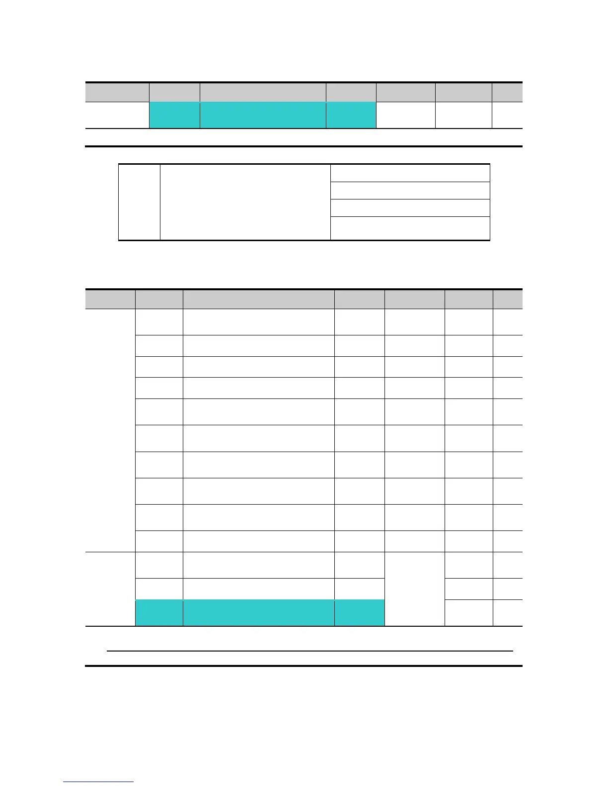
When setting carrier frequency
high,
Motor sound reduced
Inverter heat loss increased
Inverter noise increased
Inverter leakage current
increased
8.14 2
nd
motor operation
Group
Display
Parameter Name
Setting
Range
Default
Unit
Function
group 2
H81
[2nd motor accel time]
-
0 ~ 6000
5.0
sec
H82
[2nd motor decel time]
-
0 ~ 6000
10.0
sec
H83
[2nd motor base freq.]
-
30 ~ 400
60.00
Hz
H84
[2nd motor V/F pattern]
-
0 ~ 2
0
H85
[2nd motor Positive torque
boost]
-
0 ~ 15
5
%
H86
[2nd motor Negative torque
boost]
-
0 ~ 15
5
%
H87
[2nd motor stall prevention
level]
-
30 ~ 150
150
%
H88
[2nd motor electronic thermal
level for 1 min]
-
50 ~ 200
150
%
H89
[2nd motor electronic thermal
level for continuous operation]
-
50 ~ 150
100
%
H90
[2nd motor rated current]
-
0.1~100
26.3
A
I/O
group
I17
[Multi-function Input terminal
P1Function select]
-
0 ~ 27
0
~
~
I24
[Multi-function Input
terminal P8Function select]
12
7
Set the terminal among Multi-function input P1 thru P5 for second motor operation.
To define the terminal P5 as second motor operation, set I24 to 12.
For Service Call 800-848-2504

Table of Contents

Questions and Answers:

Question and Answer IconNeed help?

Do you have a question about the LSIS sv-ig5a and is the answer not in the manual?

LSIS sv-ig5a Specifications

General IconGeneral
BrandLSIS
Modelsv-ig5a
CategoryInverter
LanguageEnglish

Related product manuals