[Multi-function Input terminal
P1 select]
[Multi-function Input
terminal P8 select]
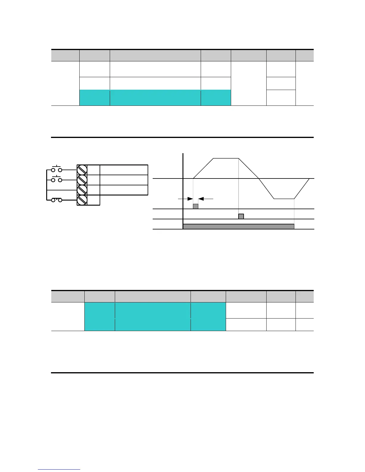
Select the terminal from P1-P8 for use as 3-Wire operation.
If P8 is selected, set I24 to 17 {3-Wire operation}.
Input signal is latched (saved) in 3-Wire operation. Therefore, inverter can be operated by
Push-button switch.
The bandwidth of pulse (t) should not be less than 50msec.
8.5 Dwell operation
In this setting, motor begins to accelerate after dwell operation is executed for dwell time
at the dwell frequency.
It is mainly used to release mechanical brake in elevators after operating at dwell
frequency.
Dwell frequency: This function is used to output torque in an intended direction. It is useful in
hoisting applications to get enough torque before releasing a mechanical brake. Rated Slip
frequency is calculated by the formula shown below.
P1
P2
P8
CM
FX : I17 = 0
RX : I18 = 1
3-Wire : I24 = 17
FX
RX
Frequency
P8 (3-Wire)
t
For Service Call 800-848-2504
For Service Call 800-848-2504

 Loading...


