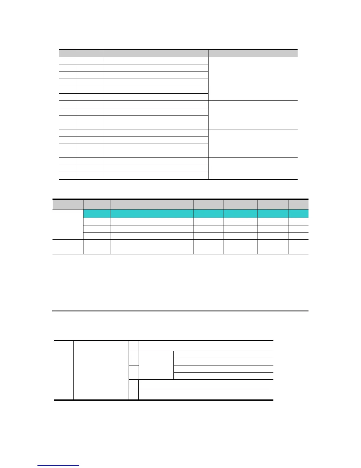
The following table shows the fault type while this function is active.
Switch above IGBT‟s U phase fault
Contact LSIS sales
representatives.
Switch below IGBT‟s U phase fault
Switch above IGBT‟s V phase fault
Switch below IGBT‟s V phase fault
Switch above IGBT‟s W phase fault
Switch below IGBT‟s W phase fault
Output short between U and W
Check for the short of inverter
output terminal, motor
connection terminal or the
proper motor connection.
Output short between U and V
Output short between V and W
Check for the ground fault
occurred at inverter output
cable or motor or motor
insulation damage.
Check for proper connection of
the motor to the inverter output
or proper motor connection.
8.16 Frequency setting and 2
nd
drive method select
Multi-function input
terminal P1 select
Drive mode 1 is used when the input set as 2
nd
source is not entered into multi-input
(I17~I24)
Drive mode 2 can input frequency setting and drive command as a 2
nd
setting value by
using multi-input terminal. In case of driving away from inverter by communication, it is
used when quit the communication and operate by inverter.
The switching method for Drive mode 1 and Drive mode 2 is as follows
If multi-input terminal set as Drive mode 2 is off, it used as Drive mode 1. If multi-input
terminal set as Drive mode 2 is on, it used as Drive mode2.
Selects the self drive in the 2
nd
switching of drv2 among the followings
Operation via Run/Stop key on the Keypad
RX: Forward/Reverse command
Operation via communication
Set to Field Bus communication
For Service Call 800-848-2504
For Service Call 800-848-2504