11.3 Installation
Connecting the communication line
Connect the RS-485 communication line to the inverter‟s (S+), (S-) terminals of the control
terminals.
Check the connection and turn ON the inverter.
If the communication line is connected correctly set the communication-related parameters as the
following: DRV-03 [Drive mode]: 3(RS485)
DRV-04 [Freq. mode]: 7(RS485)
I/O-60 [Inv. Number]: 1~250 (If more than 1 inverters are connected,
be sure to use different numbers for each inverter)
I/O-61 [Baud-rate]: 3 (9,600 bps as Factory default)
I/O-62 [Lost Mode]: 0 - No action (Factory default)
I/O-63 [Time-Out]: 1.0 sec (Factory default)
I/O-59 [Comm. Prot]: 0 - Modbus-RTU, 1 – LS BUS
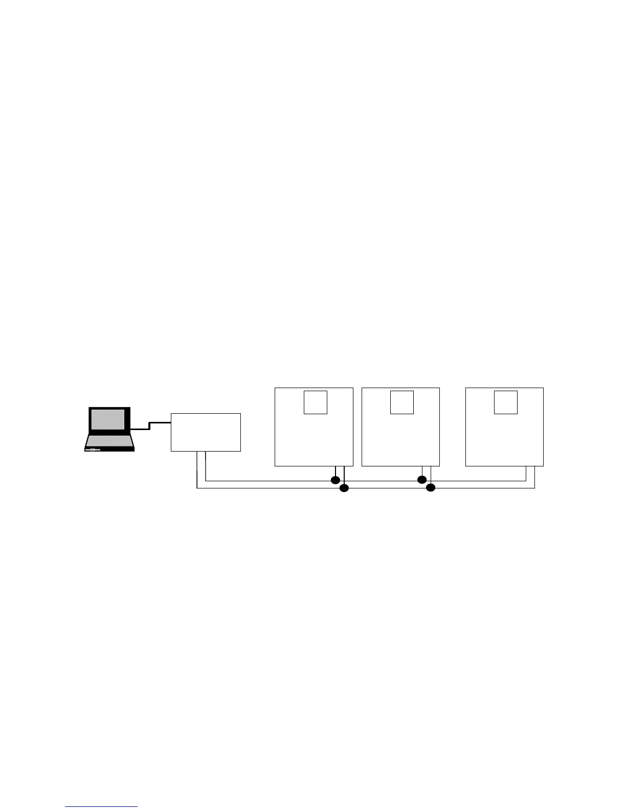
Computer and inverter connection
System configuration
- The number of drives to be connected is up to 16 drives.
- The specification of length of communication line is max. 1200m. To ensure stable communication,
limit the length below 700m.
11.4 Operation
Operating steps
Check whether the computer and the inverter are connected correctly.
Turn ON the inverter. But do not connect the load until stable communication between the computer
and the inverter is verified.
Start the operating program for the inverter from the computer.
Operate the inverter using the operating program for the inverter.
Refer to “Troubleshooting” if the communication is not operating normally.
*User program or the “DriveView” program supplied from LS Industrial Systems can be used as the
operating program for the inverter.

 Loading...


