Ex 1) The inverter determines the freq reference is lost when DRV- Frq is set to 3 (Analog
V1 input), I 16 to 1 and analog input signal is less than half the value set in I 7.
Ex 2) The inverter determines the freq reference is lost when DRV- Frq is set to 6 (V1+I), I
16 to 2 and V1 input signal is either below the value set in I 7 or I input value is less than
the I 12 value.
I62: When no frequency command is given for the time set in I63, set the drive mode as the
table below.
[Drive mode select
after loss of
frequency command]
Continuous operation with the frequency
before command loss occurs
Free run stop (output cut off)
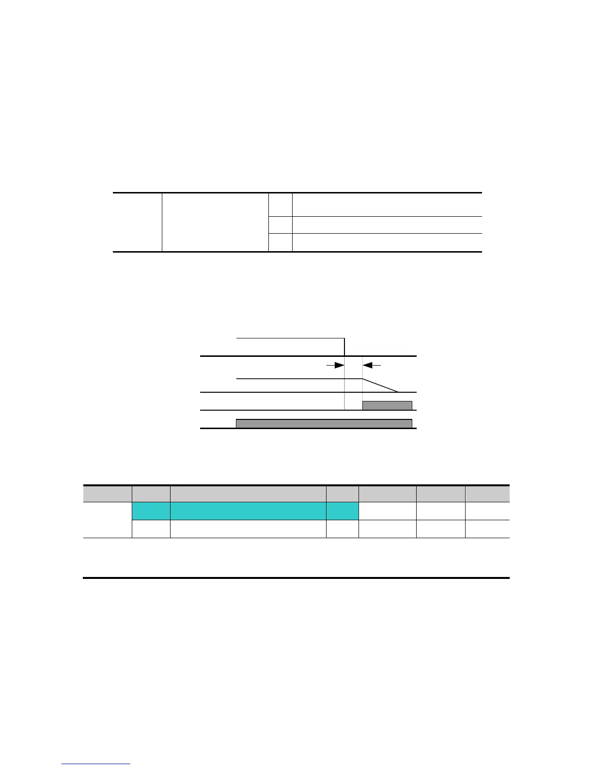
I54, I55: Multi-function output terminal (MO) or Multi-function relay output (3ABC) is used to
output information on loss of frequency command to external sequence.
Ex) when I16 is set to 2, I62 to 2, I63 to 5.0 sec and I54 to 11, respectively,
10.8 DB Resistor Enable Duty setting
Set H75 to 1.
Set %ED (Enable Duty) in H76.
Freq
MO
Run
command
Set
freq
5 sec
For Service Call 800-848-2504
For Service Call 800-848-2504