10.4 Output phase loss protection
[Input/Output phase loss
protection select]
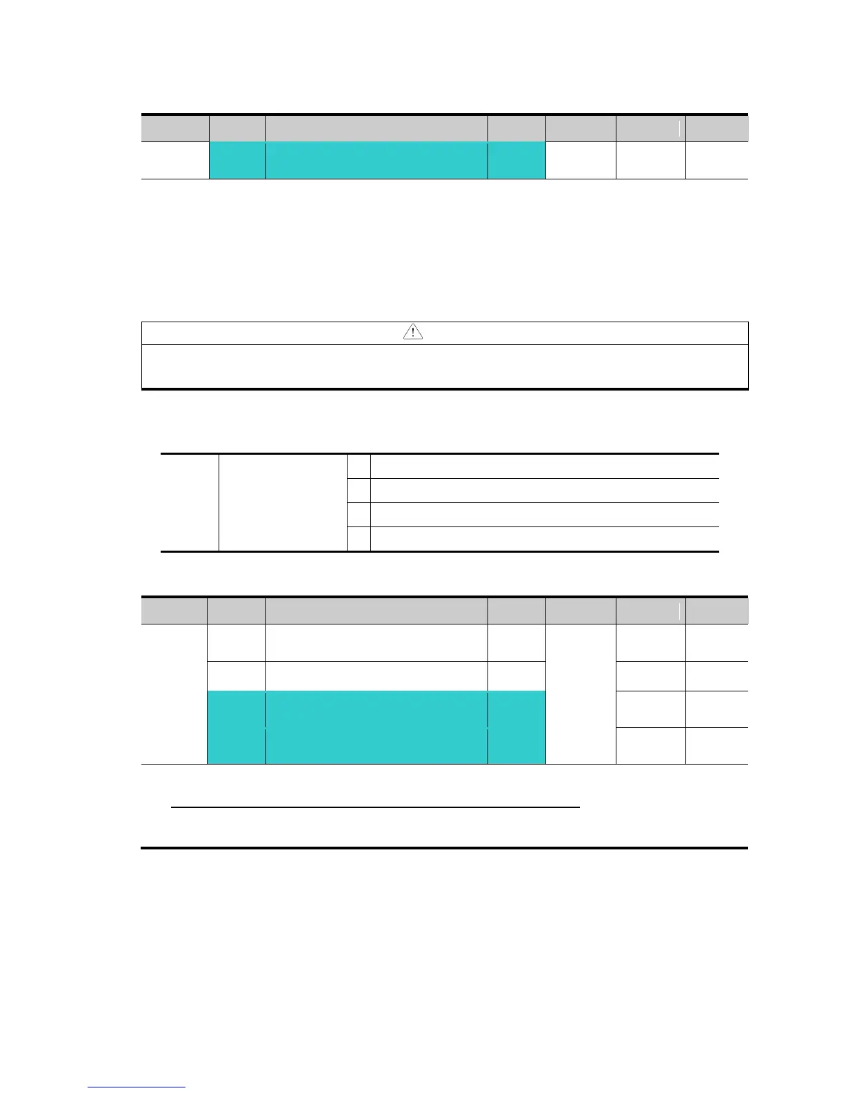
Set H19 value to 1.
Output phase loss: Inverter output is shut off at the event of more than one phase loss
among U, V and W.
Input phase loss: Inverter output is blocked at the event of more than one phase loss
among R, S and T. If there is no input phase loss, output is shut off when it is time to replace
DC link capacitor.
Set H33 [Motor rated current] correctly. If the actual motor rated current and the value of H33
are different, output phase loss protection function could not be activated.
[Input/Output
phase loss
protection select]
Output phase loss protection
Input phase loss protection
Input/output phase loss protection
10.5 External trip signal
[Multi-function input terminal P1
define]
[Multi-function input terminal
P7 define]
[Multi-function input terminal
P8 define]
Select a terminal among P1 thru P8 to output external trip signal.
Set I23 and I24 to 18 and 19 to define P7 and P8 as External A contact and B contact.
External trip signal input A contact (N.O.): Normal open contact input. When a P7 terminal set
to “Ext trip-A” is ON (Closed), inverter displays the fault and turns off its output.
External trip signal input B contact (N.C.): Normal close contact input. When a P8 terminal set
to “Ext trip-B” is OFF (Open), inverter displays the fault and turns off its output.
For Service Call 800-848-2504
For Service Call 800-848-2504