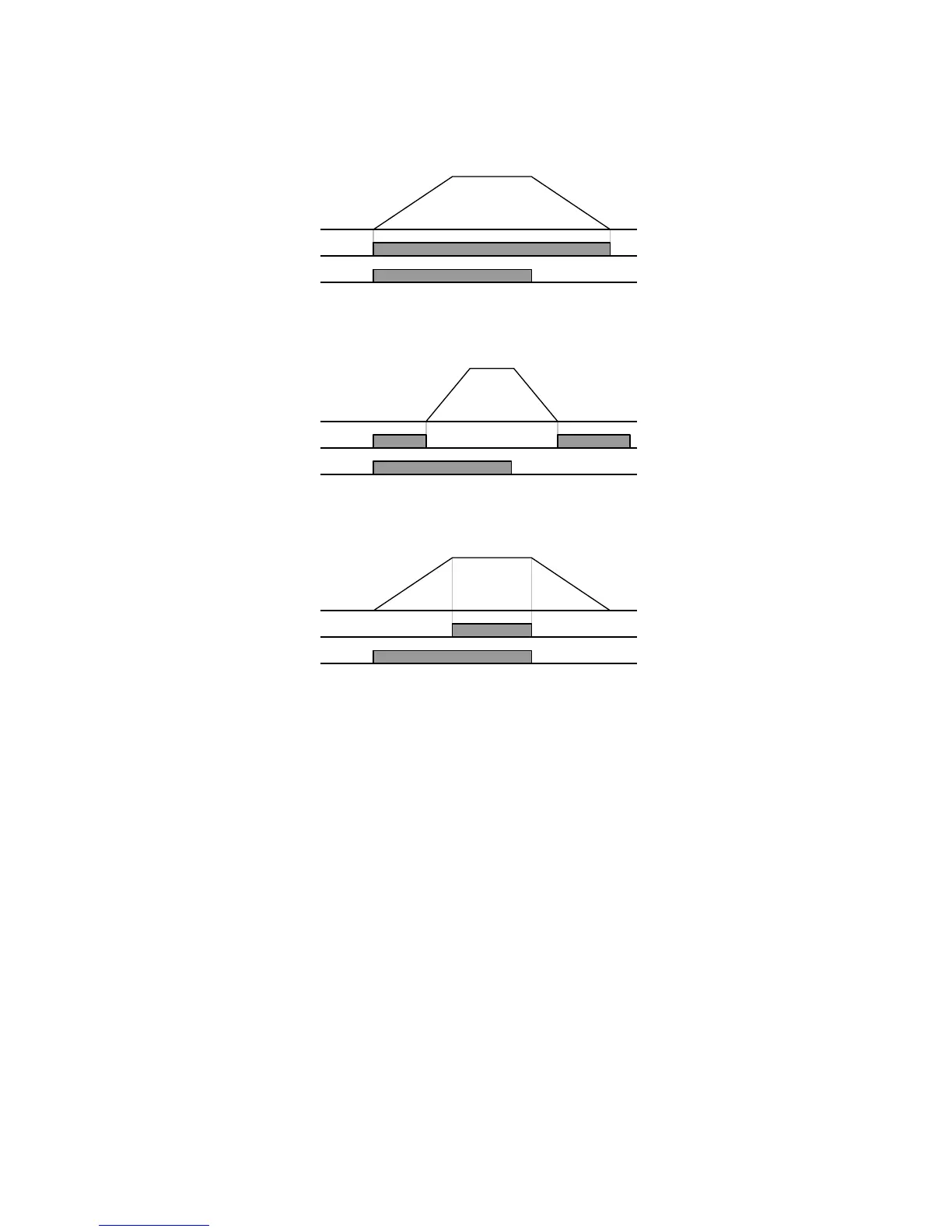
12: During operation
Activated when run command is input and inverter outputs its voltage.
13: During stop
Activated during stop without active command.
14: during constant run
Activated during constant speed operation.
15: During speed searching
Refer to page 8-17.
16: Wait time for run signal input
This function becomes active during normal operation and that the inverter waits for
active run command from external sequence.
17: Fault output
The parameter set in I56 is activated.
For example, if setting I55, I56 to 17 and 2, respectively, Multi-function output relay
will become active when trip other than “Low voltage trip” occurred.
18: Cooling fan trip alarm
Used to output alarm signal when H78 is set to 0(constant operation at cooling fan
trip). Refer to page 8-31.
19: Brake signal
It is used for signal output when set for use of external brake signal. Refer to the page
8-26.

 Loading...


