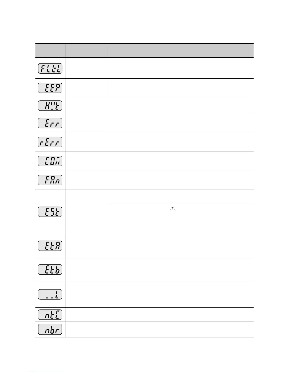
Fault Display and Information
Self-diagnostic
malfunction
Displayed when IGBT damage, output phase short, output phase
ground fault or output phase open occurs.
Displayed when user-setting parameters fails to be entered into
memory.
Displayed when an error occurs in the control circuitry of the
inverter.
Displayed when the inverter cannot communicate with the
keypad.
Remote keypad
communication
error
Displayed when inverter and remote keypad does not
communicate each other. It does not stop Inverter operation.
Displayed after Inverter resets keypad when keypad error occurs
and this status is maintained for a certain time.
Displayed when a fault condition occurs in the inverter cooling
fan.
Used for the emergency stop of the inverter. The inverter instantly
turns off the output when the EST terminal is turned on.
The inverter starts to regular operation when turning off the EST
terminal while FX or RX terminal is ON.
External fault A
contact input
When multi-function input terminal (I17-I24) is set to 18 {External
fault signal input: A (Normal Open Contact)}, the inverter turns off
the output.
External fault B
contact input
When multi-function input terminal (I17-I24) is set to 19 {External
fault signal input: B (Normal Close Contact)}, the inverter turns off
the output.
Operating
method when the
frequency
command is lost
When inverter operation is set via Analog input (0-10V or 0-20mA
input) or option (RS485) and no signal is applied, operation is
done according to the method set in I62 (Operating method when
the frequency reference is lost).
When NTC is not connected, outputs are cut off.
When Break control, if rating current flows below than set value,
cut off the output without break open.
For Service Call 800-848-2504
For Service Call 800-848-2504

 Loading...


