Chapter14 Analog Output Module (XBF-DV04C/XBF-DC04C)
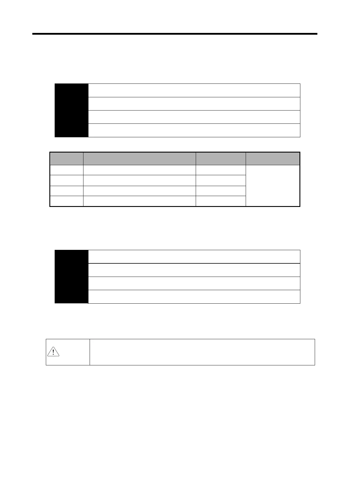
7) Channel error
Show the error code of each channel.
When two error or more are happened, the high priority of error code will be saved.
Channel 1 error code
Channel 2 error code
Address
No. 14
Address
No. 15
Channel 3 error code
Address
No. 16
Channel 0 error code
Address
No. 13
Bit 15 Bit 14 Bit 13
Bit 12
Bit 11
Bit 10
Bit 9
Bit 8
Bit 7
Bit 6
Bit 5
Bit 4
Bit 3
Bit 2 Bit 1 Bit 0
Details
Error code
order of priority
Remarks
0 Normal operation
−
#:CH number 0-3
31# Excess error of output range setting 2
41# Excess error of digital input value range 1
51# Excess error of interpolation method range 3
8) Interpolation operation value
Show the interpolation operation value of each channel.
Channel 1 Interpolation operation value
Channel 2 Interpolation operation value
Address
No. 18
Address
No. 19
Channel 3 Interpolation operation value
Address
No. 20
Channel 0 Interpolation operation value
Address
No. 17
Bit 15 Bit 14 Bit 13 Bit 12
Bit 11 Bit 10 Bit 9 Bit 8 Bit 7 Bit 6 Bit 5 Bit 4 Bit 3 Bit 2 Bit 1 Bit 0
9) System area
The system area (after No. 22) is prohibited to read/write.
Warning
If this area is changed, malfunctions or breakdowns will be happened. So do not
control this area.
14 - 35
 Loading...
