EasyManuals Logo

LSIS XBF-AD04A User Manual

LSIS XBF-AD04A
618 pages
To Next Page IconTo Next Page
To Previous Page IconTo Previous Page
Page #449 background imageLoading...
Page #449 background image
XGB Analog edition manual
12.12 Configuration and Function of Internal Memory
It describes the configuration and function of internal memory
12.12.1 Data I/O area (U device)
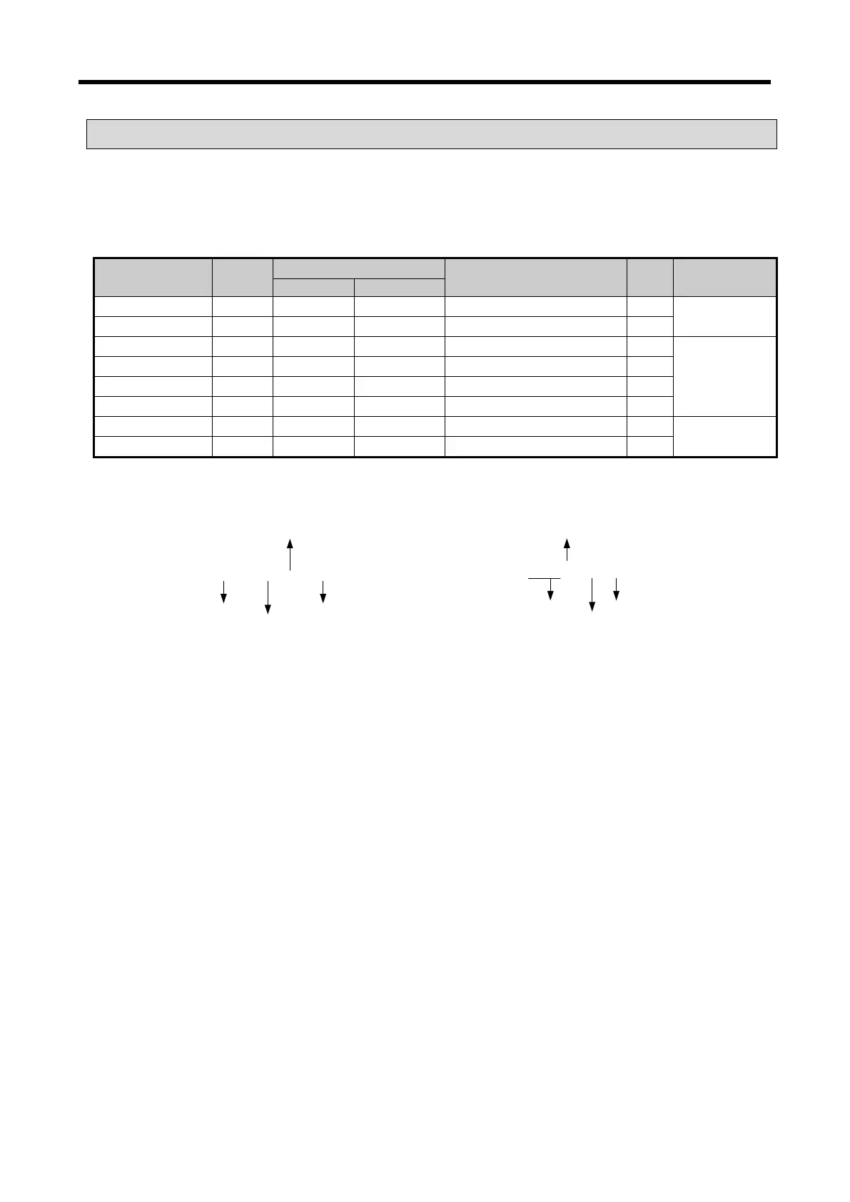
(1) Data sent from module to XGB main unit (XGB PLC input area, read only
Device
assignment
Type
Device assignment
Comment R/W
Signal
direction
XBC
IEC
_0y_ERR
BIT
U0x.00.E
%UX0.y.14
Module H/W error
R
TC02A→CPU
_0y_RDY
BIT
U0x.00.F
%UX0.y.15
Module Ready
R
_0y_CH0_ACT
BIT
U0x.01.0
%UX0.y.16
CH 0 running
R
TC02A→CPU
_0y_CH1_ACT
BIT
U0x.01.1
%UX0.y.17
CH 1 running
R
_0y_CH0_BOUT
BIT
U0x.01.4
%UX0.y.20
CH 0 disconnection
R
_0y_CH1_BOUT
BIT
U0x.01.5
%UX0.y.21
CH 1 disconnection
R
_0y_CH0_TEMP
WORD
U0x.04
%UW0.y.4
CH 0 temp. conversion value
R
TC02A→CPU
_0y_CH1_TEMP
WORD
U0x.05
%UW0.y.5
CH 1 temp. conversion value
R
- In the device allocation, the small letter ‘y’ is the No. of the slot where the module is installed.
- For example, to read the ‘CH0 Temperature Value’ of the TC module installed in the slot 9, write in
U09.05. (%UW0.9.4 for IEC types)
Device Type
U 0 9 . 0 4
Slot No.
Word
[XBC type]
Word classifier
Device Type
Slot No.
Base No
Word
[IEC type]
% U W 0 . 9 . 4
.
12 - 24

Table of Contents

Questions and Answers:

Question and Answer IconNeed help?

Do you have a question about the LSIS XBF-AD04A and is the answer not in the manual?

LSIS XBF-AD04A Specifications

General IconGeneral
BrandLSIS
ModelXBF-AD04A
CategoryController
LanguageEnglish

Related product manuals