Chapter 2 Analog Input Module (XBF-AD04A)
2 - 13
2.8 Wiring
2.8.1 Precaution for wiring
(1) Don’t let AC power line near to A/D conversion module’s external input sign line. With an enough
distance kept away between, it will be free from surge or inductive noise.
(2) Cable shall be selected in due consideration of ambient temperature and allowable current,
whose size is not less than the max. cable standard of AWG22 (0.3
㎟).
(3) Don’t let the cable too close to hot device and material or in direct contact with oil for long, which
will cause damage or abnormal operation due to short-circuit.
(4) Check the polarity when wiring the terminal.
(5) Wiring with high-voltage line or power line may produce inductive hindrance causing abnormal
operation or defect.
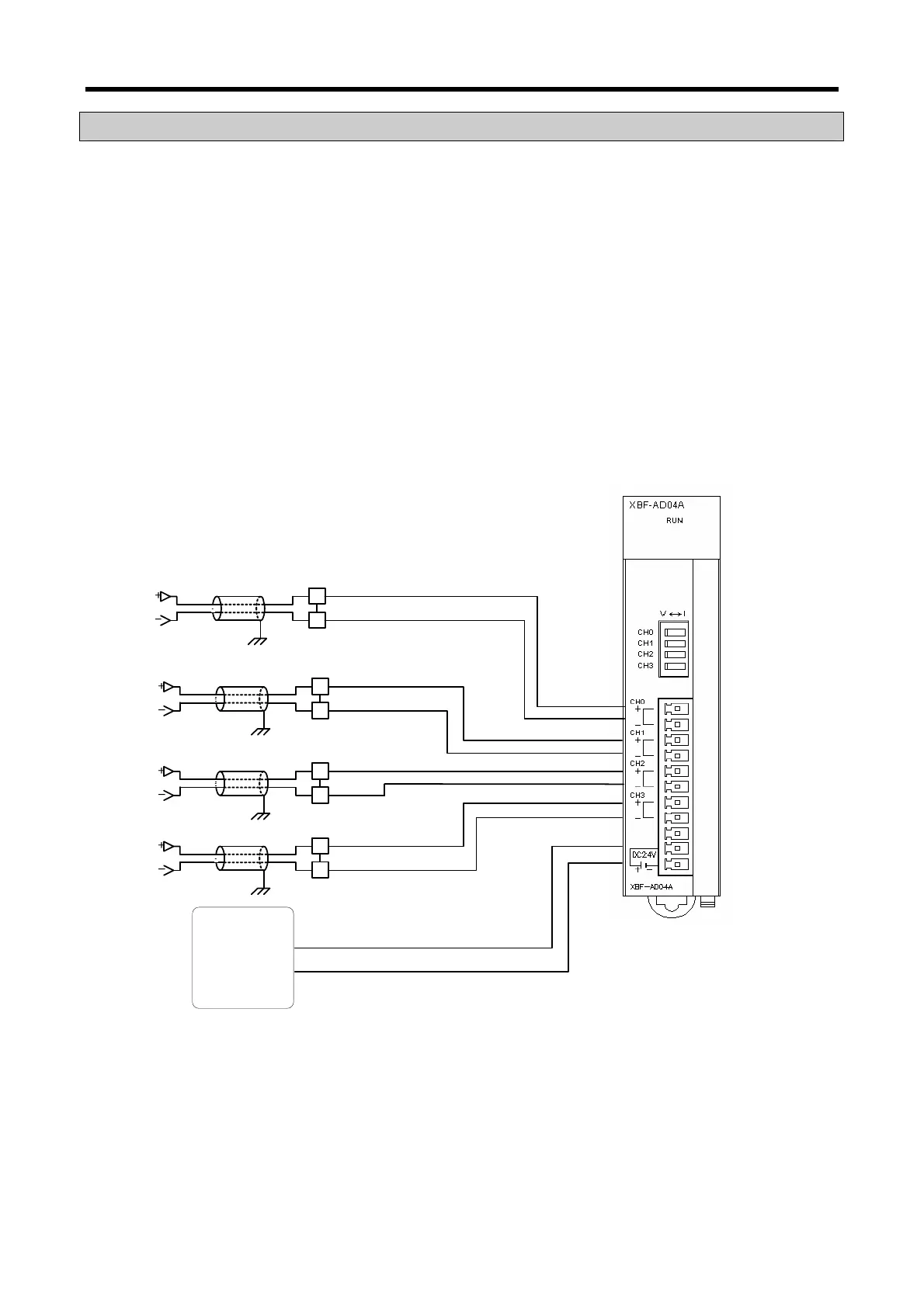
2.8.2 Wiring examples
(1) Example of voltage wiring
- In case of voltage/current input, wiring is same. Adjust the voltage/current setting switch
according to the case.
+
-
CH0
+
-
CH2
+
-
CH1
+
-
CH3
DC power
(For analog
supply)
CH0+
CH0-
CH1+
CH1-
CH2+
CH2-
CH3+
CH3-
DC24V+
DC24V-
(a) Input resistance of current input circuit is 250 Ω (typ.).
(b) Input resistance of voltage input circuit is 1 MΩ (min.).
(c) Enable the necessary channel only.
(d) Analog input module doesn’t support power for input device. Use the external power
supplier.