XGB Analog edition manual
15 - 42
The paragraph explains example programs regarding the directions of XGB built-in PID function.
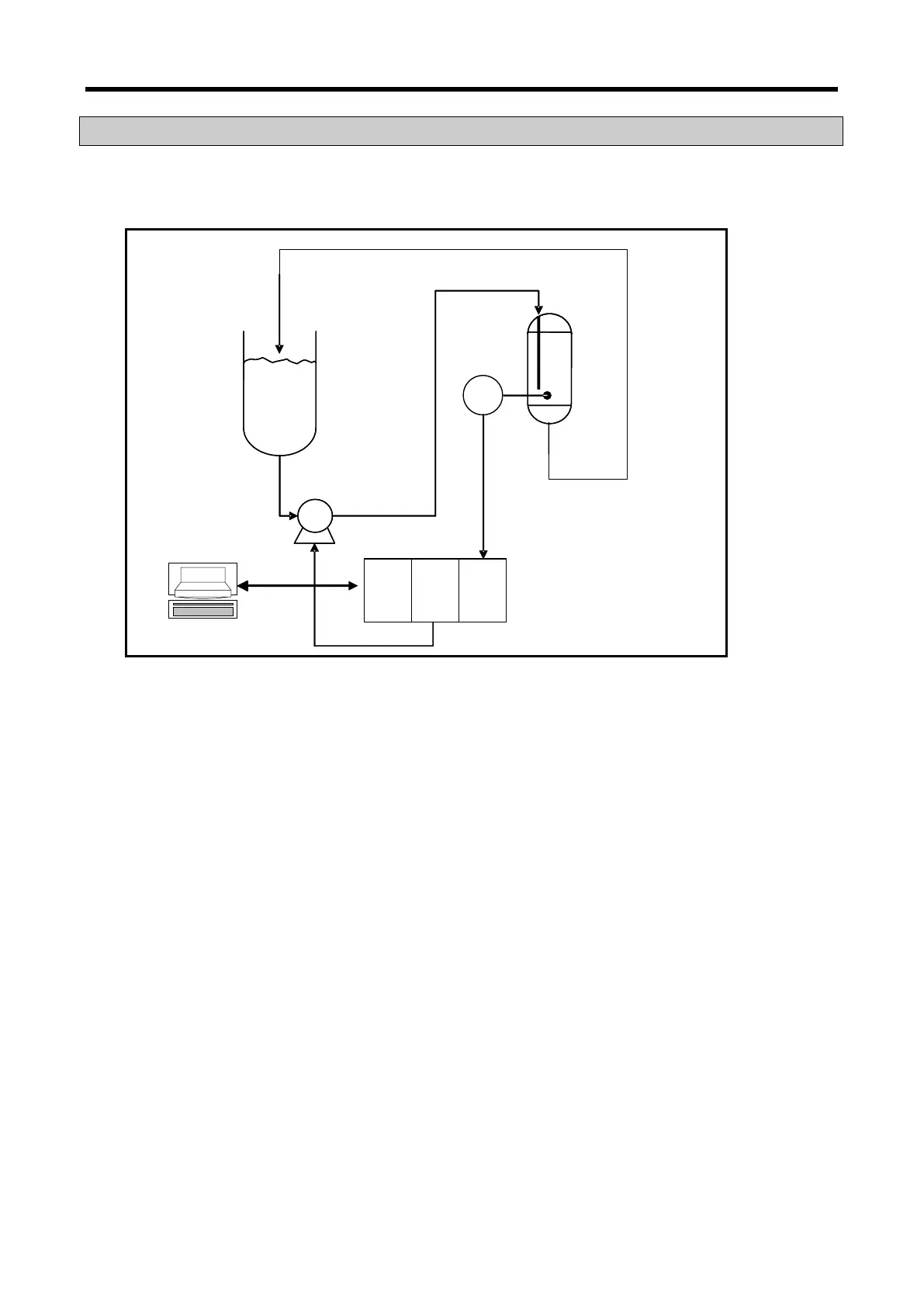
The example programs are explained with water level system as illustrated in 15.17.
[ Figure 15.17 Example of water level control system ]
15.5.1 System structure
The example system in figure is an example of a system to control a pail’s water level to a desired
level. The pail’s water level is sensed by a water level sensor and entered to A/D input module while
PID control operation result, MV is output to a pump through D/A output module, controlling a pump’s
rotation velocity, regulating the water amount flowing into a pail and regulating the water level as
desired. Each mechanism is explained as follows.
(1) XGB basic unit
The XGB basic unit operates by PID control operating PID control operation. It receives PV from
A/D input module (XBF-AD04A), executes the built-in PID control operation, output the MV to D/A
(XBF-DV04A) and executes PID control.
(2) A/D input module (XBF-AD04A)
It functions as receiving PV of an object to control from a water level sensor and delivering it to
basic unit. XBF-AD04A is a 4CH analog input module and settings of analog input types and
scopes can be changed in the I/O parameter setting window appeared when selecting I/O
parameter in the parameter item of project window. For more information, refer to Analog I/O
Module.
(3) D/A output module (XBF-DV04A)
It functions as delivering control MV from basic unit to a drive (pump). XBF-DV04A is a 4CH
analog voltage output module and ranges 0 ~ 10V. For detail setting, refer to Analog I/O Module.