Chapter 13 Analog Input Module (XBF-AD04C)
13.3 Name of each Part and Functions
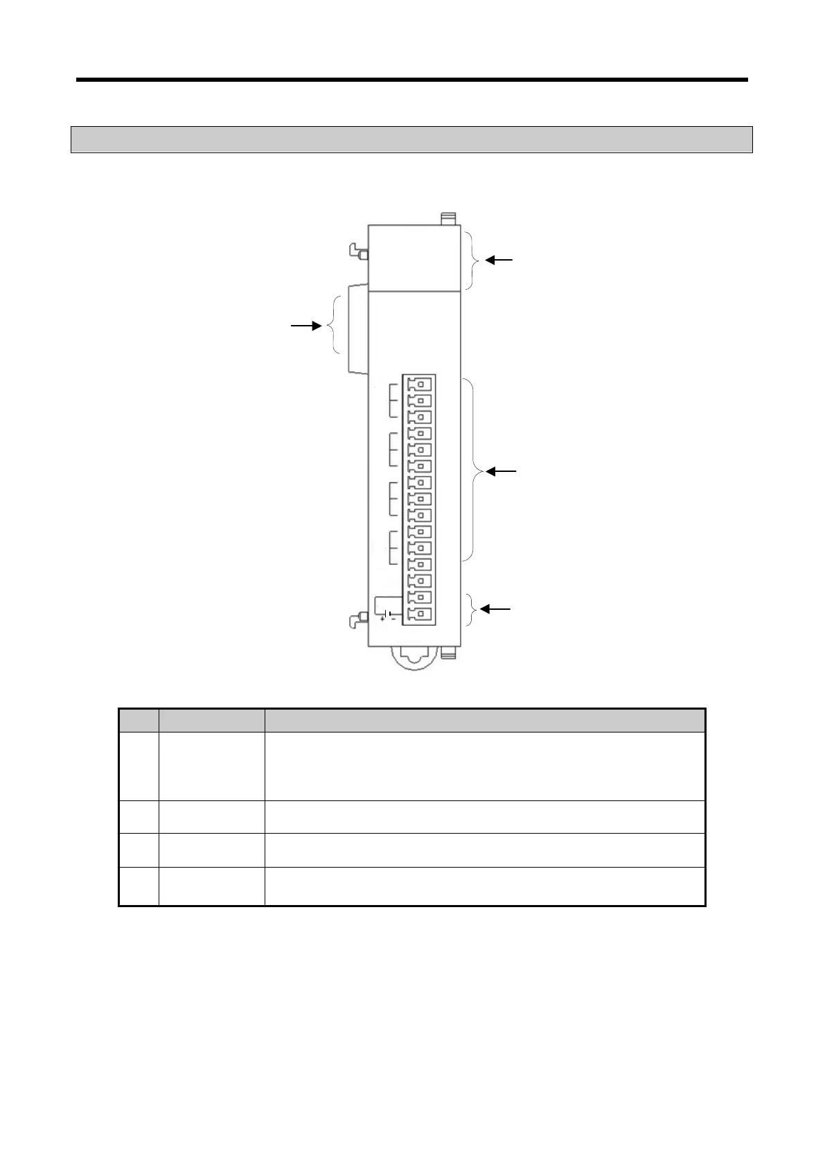
Respective designations of the parts are as described below.
①
②
③
④
XBF-AD04C
RUN
XBF-AD04C
DC24V
-10~10V
0~20mA
V0+
I0+
COM0
V1+
I1+
COM1
V2+
I2+
COM2
V3+
I3+
COM3
① RUN LED
▶
Displays the operation status of module
On: Operation normal
Blinks: Error occurs (Flickering 1s intervals)
Off: Power off or module error
②
Terminal ▶ W iring terminal block to connect with external device
③
▶ Terminal for supplying the external DC24V
④
Ext. Connector ▶ Connector for extension modules.
13 - 5