XGB Analog edition manual
6.7.1 Precautions for Wiring
(1) Keep the I/O signal lines of the analog I/O module away from AC power line. Otherwise, the
surge or induction noise of the AC line may affect the module.
(2) The cable should be selected taking ambient temperature and allowable current into
consideration. Recommended cable is AWG22 (0.3㎟) or higher grade.
(3) Keep the cables away from heat source or oil. Otherwise, short-circuit, damage, or malfunction
of the module may occur.
(4) Check polarity at terminal block connection.
(5) Keep the cables away from high voltage line or power line to avoid malfunction or failure of the
module by induction.
6.7.2 Exemplary Analog Input Wiring
(1) Input resistance of the current input circuit is 250 Ω (typ.).
(2) Input resistance of the voltage input circuit is 1 MΩ (min.).
(3) Set only the channels to be used up for operation.
(4) Analog I/O module does not provide power supply to external input device. Use external power
supply.
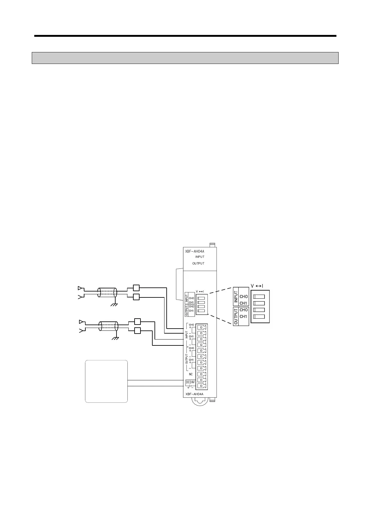
(5) Exemplary analog input wiring
Same wiring scheme is applied to voltage and current inputs, except that voltage/current
setting switch must be set up accordingly.
+
-
CH0
+
-
+
-
CH1
+
-
DC power
(for analog module)
CH0+
CH0-
CH1+
CH1-
DC24V+
DC24V-
Voltage/Current
Selection
Switch
6 - 18