XGB Analog edition manual
Describes configuration and function of internal memory
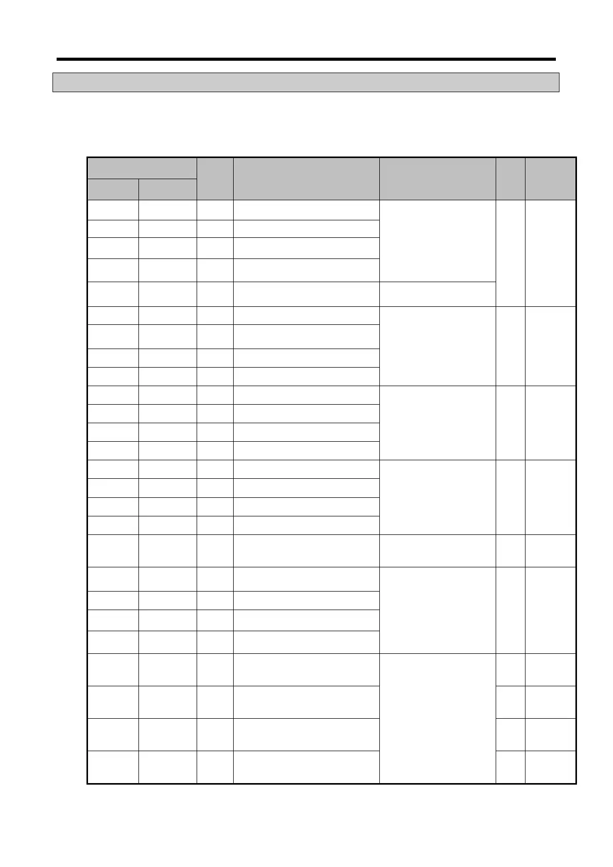
14.11.1 Data I/O area
Describes data I/O area of analog output module.
Device assigned
Type Description Details R/W
Direction
of signal
XBM/XBC XEC
U0y.00.0 %UX0.y.0 BIT Channel0 Error
Parameter setting
On(1): Setting error
Off(0): Setting normal
R
DV04C /
DC04C →
CPU
U0y.00.1 %UX0.y.1 BIT Channel1 Error
U0y.00.2 %UX0.y.2 BIT Channel2 Error
U0y.00.3 %UX0.y.3 BIT Channel3 Error
U0y.00.F %UX0.y.15 BIT Module Ready
On(1): Ready for action
U0y.01.0 %UX0.y.16 BIT Channel0 In operation
Channel operation
On(1): Operation
Off(0): Stop
R
DV04C /
DC04C →
CPU
U0y.01.1 %UX0.y.17 BIT Channel1 In operation
U0y.01.2 %UX0.y.18 BIT Channel2 In operation
U0y.01.3 %UX0.y.19 BIT Channel3 In operation
U0y.01.8 %UX0.y.24 BIT Channel 0 Interpolation output
Interpolation output status
On(1): Interpolation output
Off(0): Stop
R
DV04C /
DC04C →
CPU
U0y.01.9 %UX0.y.25 BIT Channel 1 Interpolation output
U0y.01.A %UX0.y.26 BIT Channel 2 Interpolation output
U0y.01.B %UX0.y.27 BIT Channel 3 Interpolation output
U0y.01.C %UX0.y.28 BIT Channel0 disconnection detection
Disconnection detection
On(1): Disconnection
detection
Off(0): Stop
(Only for XBF-DC04C)
R
DC04C →
CPU
U0y.01.D %UX0.y.29 BIT Channel1 disconnection detection
U0y.01.E %UX0.y.30 BIT Channel2 disconnection detection
U0y.01.F %UX0.y.31 BIT Channel3 disconnection detection
U0y.02 %UW0.y.2 WORD Output enable setting Output status setting W
DC04C ↔
U0y.02.0 %UX0.y.32 BIT Channel0 Output enable setting
Output enable setting
On(1): Output enable
Off(0): Output prohibition
W
DV04C /
DC04C ↔
CPU
U0y.02.1 %UX0.y.33 BIT Channel1 Output enable setting
U0y.02.2 %UX0.y.34 BIT Channel Output enable setting
U0y.02.3 %UX0.y.35 BIT Channel3 Output enable setting
U0y.03 %UW0.y.3 WORD CHannel0 Input value
Output conversion value
W
DC04C ↔
U0y.04 %UW0.y.4 WORD Channel1 Input value W
DC04C ↔
U0y.05 %UW0.y.5 WORD Channel2 Input value W
DC04C ↔
U0y.06 %UW0.y.6 WORD Channel3 Input value W
DC04C↔
14 - 28