Chapter14 Analog Output Module (XBF-DV04C/XBF-DC04C)
Explain the test and measure method of breakdown while using the analog input module.
14.13.1 Checking the LED status in case of error
The analog input module has a LED and is able to check whether there is error of the module
through the sign of LED.
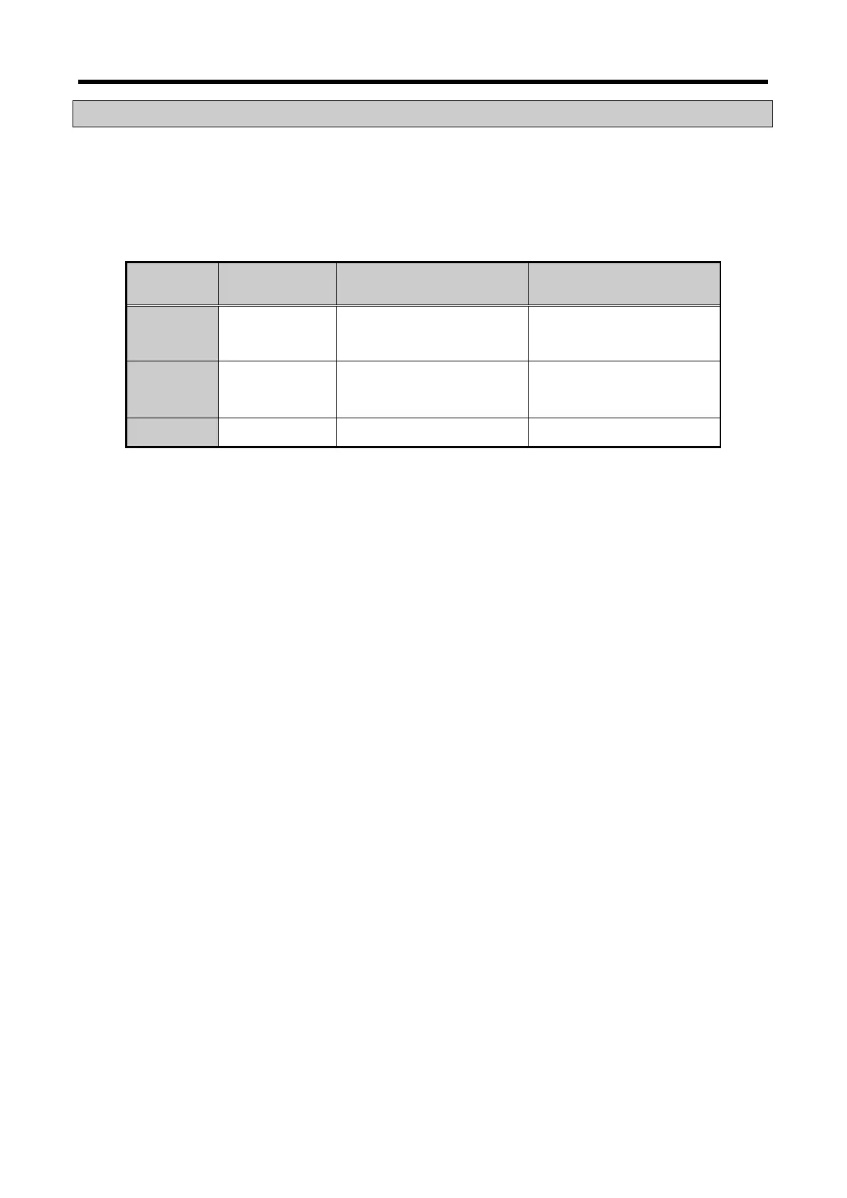
Item Normal Status When CH is disconnected
When parameter setting
is error
LED Light on Flickering 1s intervals
Flickering 1s intervals
(When the output parameter
setting is error)
Module
Operation
Operation of all
Operation of all functions
Operation of all functions
(Operation by basic value of
parameter)
Measure − Check output wiring Check parameter setting
14.13.2 Check the module status
The status of analog input module (Module type/information/OS version) can be checked through the
system monitor of XG5000.
1) The order of execution
It can be implemented through one of the methods among next items.
(1)[Monitor] -> [System Monitor] -> Click the right button of mouse on the painting of module.
-> [Module Information]
(2)[Monitor] -> [System Monitor] -> Double click the painting of module
(3)[Monitor] -> [Special Module Monitor] -> [XBF-AD04C] Selection ->Click the module information
(4)[Online] -> [I/O Information] -> [XBF-AD04C] Selection -> Click the details
(5)[Online] -> [I/O Information] -> [XBF-AD04C] Double click
2) Module information
(1) Module Name: Information of recently equipped module device is shown.
(2) OS Version: OS version of module is shown.
(3) OS Update Date: The OS prepared date of module is shown.
(4) Module status: The present error code is shown.
14 - 39