Chapter 15 PID Function (Built-in function)
15 - 37
15.4.4 Auto-tuning flag
The parameters set in the XGB series auto-tuning function are saved to the flash memory of basic unit.
Such parameters are moved to K area for auto-tuning function as soon as PLC enters to RUN mode
from STOP. Auto-tuning operation using auto-tuning command is achieved by data in K area. At the
moment, if PLC is changed to RUN again after being changed to STOP, it takes the parameters in
flash memory to K area, so the data changed in K area is lost. Therefore, to continuously apply the
parameters adjusted in K area, it is necessary to write the parameters set in K area into flash memory
by using WRT command. (In case of IEC type, APM_WRT function block)
(1) Auto-tuning flag configuration
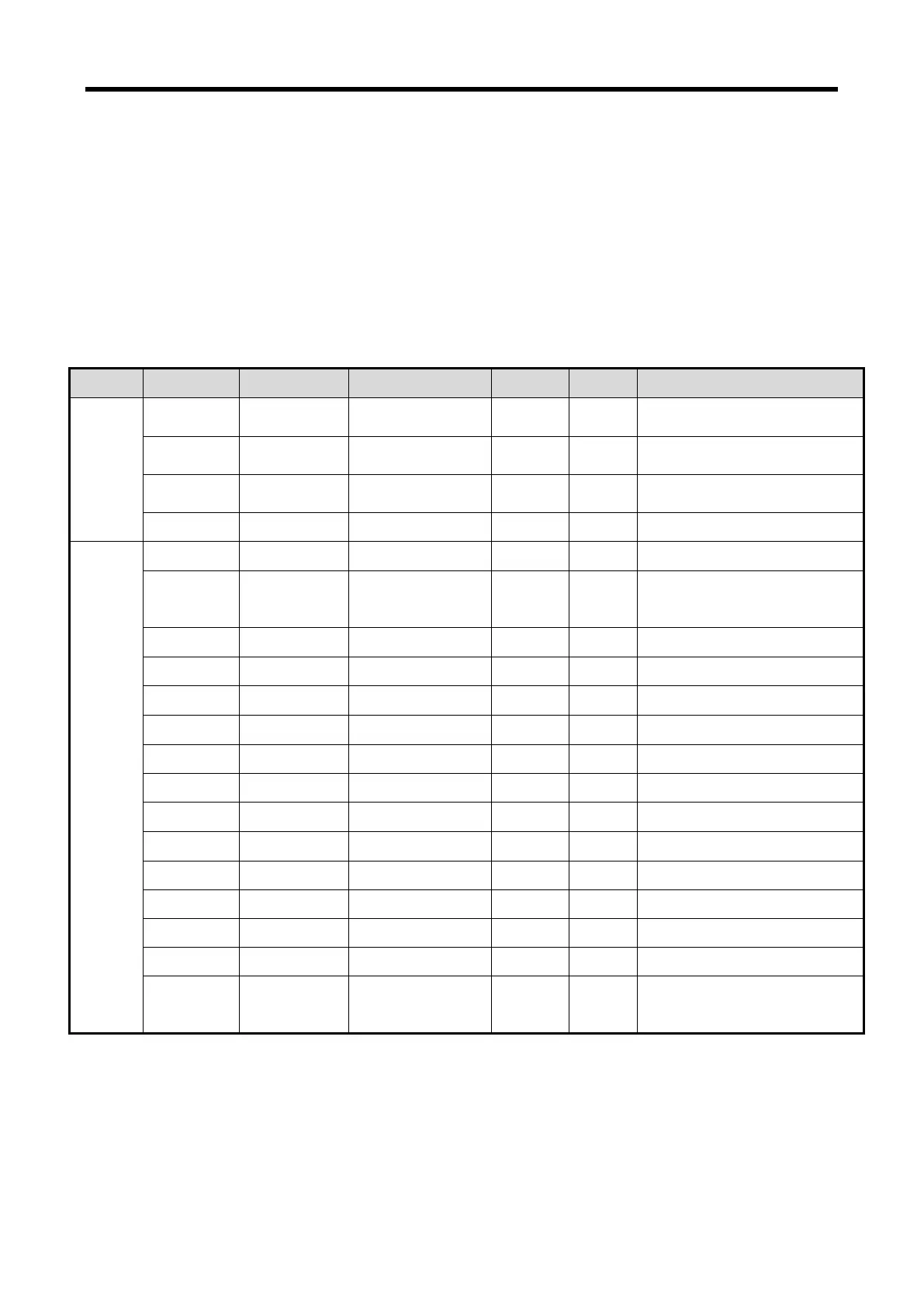
The K area flags of XGB series auto-tuning function are summarized in Table 15.12.
Auto-tuning direction(0:forward,
1:reverse)
PWM output enable(0:disable,
1:enable)
Auto-tuning
error(0:normal,1:error)
AT operation cycle
(T_s)[0.1msec]
AT auto-tuning status indication
AT result proportional coefficient
AT result differential time
[Table 15.12 K area flags for auto-tuning]
K1856 ~ K1859 areas (In case of IEC type, %KW1856~%KW1859) are the common bit areas for
auto-tuning and each bit represents auto-tuning loop status respectively. K1860~K1879 areas save
the setting and status of loop 0 as the K area for auto-tuning loop 0. In the area, the parameters
such as PV, operation cycle and etc set in the built-in parameter window are saved and the XGB
built-in auto-tuning function executes auto-tuning by the device values and saves the results into the
K areas.