p/n 18603-001, Rev. C LTV
®
1200/1150 Ventilator Service Manual Page 8-45
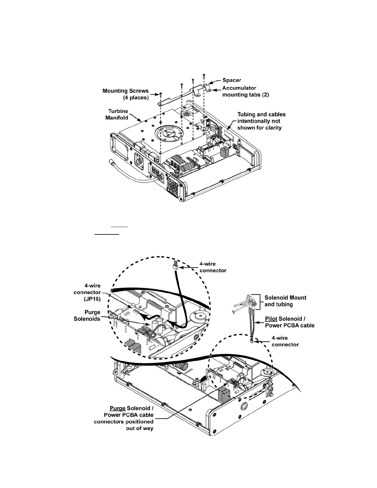
Solenoid Mount and Subassemblies Installation:
1)
Position the Manifold to Back Panel Spacer P/N 18142-001 on the Turbine Manifold,
align the mounting holes, insert four 7/16” pan-head screws and torque tighten each to
20 in-oz (0.14Nm).
2) Position the Purge Solenoid/Power PCBA cable connectors temporarily out of the way
(as shown) and route the 4-wire cable on the Pilot Solenoid/Power PCBA cable
assembly under
the Accumulator mounting tab on the Manifold to Back Panel Spacer
and between
the Purge Solenoids and the Turbine Manifold. Attach the connector to
the 4-wire connector (JP16) on the Power PCBA. The connector is keyed to fit only one
way and will snap into place when properly aligned.