p/n 18603-001, Rev. C LTV
®
1200/1150 Ventilator Service Manual Page 8-67
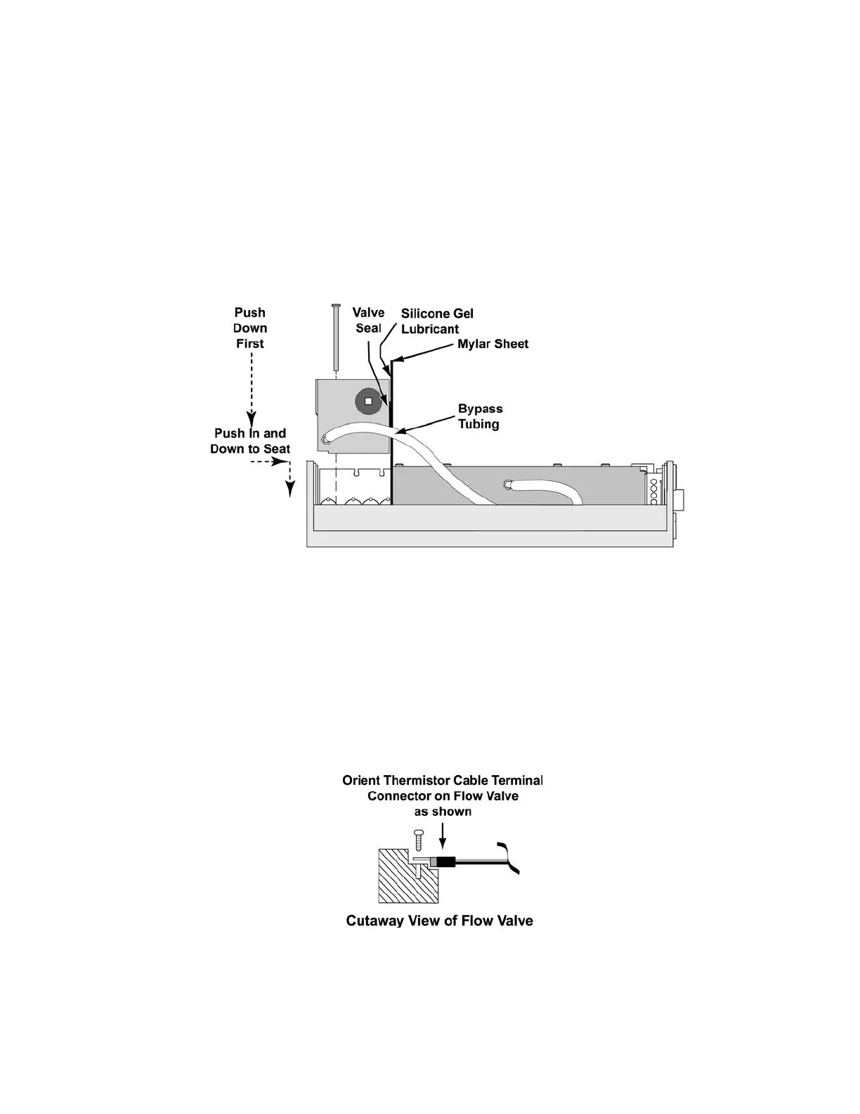
To replace the flow valve assembly:
1) Connect the bypass tubing to the connector at the base of the new flow valve.
2) Apply a small amount of silicone gel lubricant to the flat surface area on the valve
sealing gasket. Apply a small amount of silicone gel lubricant to the Mylar sheet
insertion tool.
3) Place the Mylar sheet insertion tool against the turbine manifold where it will contact the
flow valve sealing gasket. This will allow the flow valve to be slipped into place without
rolling or damaging the valve sealing gasket.
4) Slide the new flow valve assembly into place. Be sure not to catch any tubing or wiring
under the manifold while it is being installed. The flow valve must be lined up so the
screw seats on the inside of the upper weldment fit into the keyed slots in the bottom of
the flow valve assembly.
5) Once the screw seats are in the slots, the flow valve body must be pressed towards the
turbine manifold and then down so the screw seats slip into the mating holes in the
bottom of the flow valve assembly.
6) Attach the terminal connector of the Thermistor Cable P/N 11399 with the orientation
crimp side down as shown below. Screws should be torqued to 60 in-oz (0.42 Nm).