p/n 18603-001, Rev. C LTV
®
1200/1150 Ventilator Service Manual Page 8-85
17) Hold the ribbon cable out of the way and install the new main board. Be careful not to
scratch the ribbon cable with the edge of the board. When the main board is
correctly aligned, the LEDs and displays will pop into place in the cutouts in the upper
weldment.
18) Replace the three (3) 1/4” pan-head main board mounting screws (P/N 10435) and
reinsert the two (2) 3/16” hex standoffs (P/N 11543) into the holes on the main board on
each side of the 64-pin header. Torque-tighten screws and hex standoffs to 60 in-oz
(0.42 Nm).
19) Open the ZIF connector on the main board as shown in the illustration on the previous
page. Carefully slide the keypad ribbon cable
into the open ZIF connector on the main
board. Once the ribbon cable is fully inserted, slide the ZIF connector closed.
CAUTION
Damage to the ribbon cable - Attempting to insert the ribbon cable into a closed ZIF connector will
damage the ribbon cable and you may have to replace the front membrane panel.
20) Reattach the memory board to the main board (see instructions on page 8-88).
21) Replace the power board, (see instructions on page 8-101).
22) Replace the alarm sounder, (see instructions on page 8-55).
23) Reconnect the 4-wire rotary switch connector, and 2-wire sounder connectors to the
power board. These keyed connectors can only be installed in one direction and will
snap into place when properly connected.
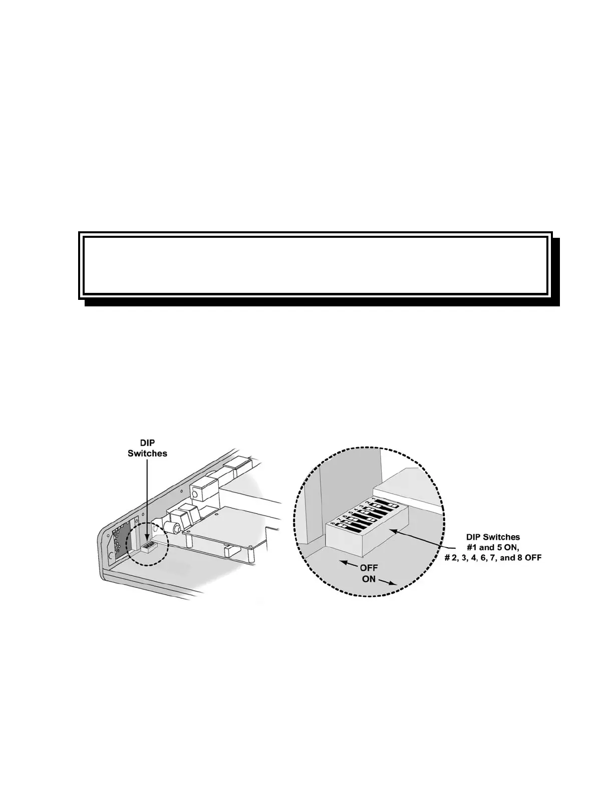
24) With main board, power board, and memory boards installed, move dip switches #1 and
#5 to the ON position and all other dip switches to the OFF position.
25) Connect the AC adapter to the power board. Press the ON button and all LEDs will be
illuminated. Check the LED alignment. If alignment is required, remove the AC power
adapter then adjust the main board and LEDs as needed.