Page 8-108 LTV
®
1200/1150 Ventilator Service Manual p/n 18603-001, Rev. C
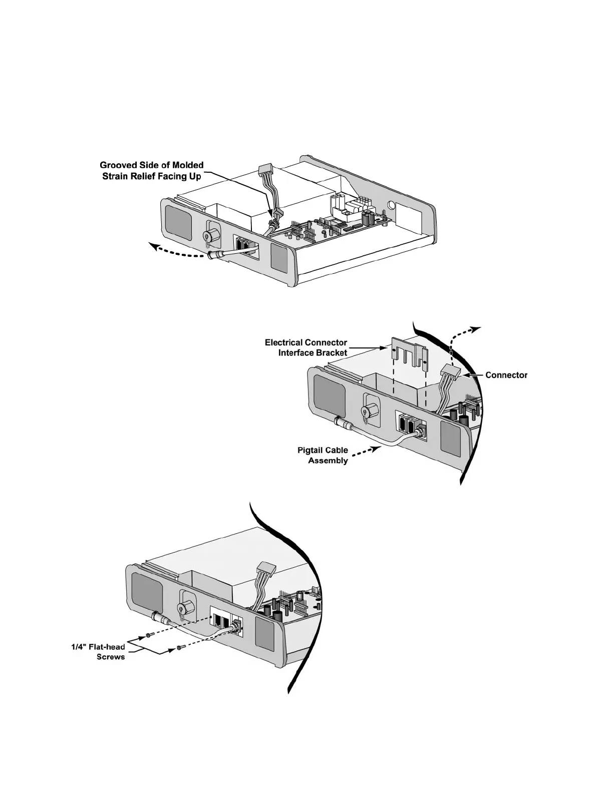
10) Insert the cylindrical connector-end of a pigtail cable assembly over the power board
and through the keyed-round hole of the upper weldment from the inside of the upper
weldment.
11) Slide the pigtail cable assembly through the hole in the upper weldment until the strain
relief protrudes through the keyed-round hole in the upper weldment.
12) Slide the electrical connector
interface bracket down through
the recess in the molded strain
relief of the pigtail cable
assembly.
13) Insert and thread two 1/4” flat-
head screws (P/N 10430) through
holes in the left sidewall of the
upper weldment and into the
threaded bosses on the electrical
connector interface bracket.
Torque-tighten both screws to 60
in-oz (0.42 Nm).
14) Plug the 4-wire connector of the
pigtail cable assembly onto the
JP6 connector on the power
board. Fold the wires of the
pigtail cable assembly back
toward the cavity for the internal
battery.