ASSEMBLY
Radio Installation
Provision
ha
s
been
mad
e
for
easy
installation of a
radio:
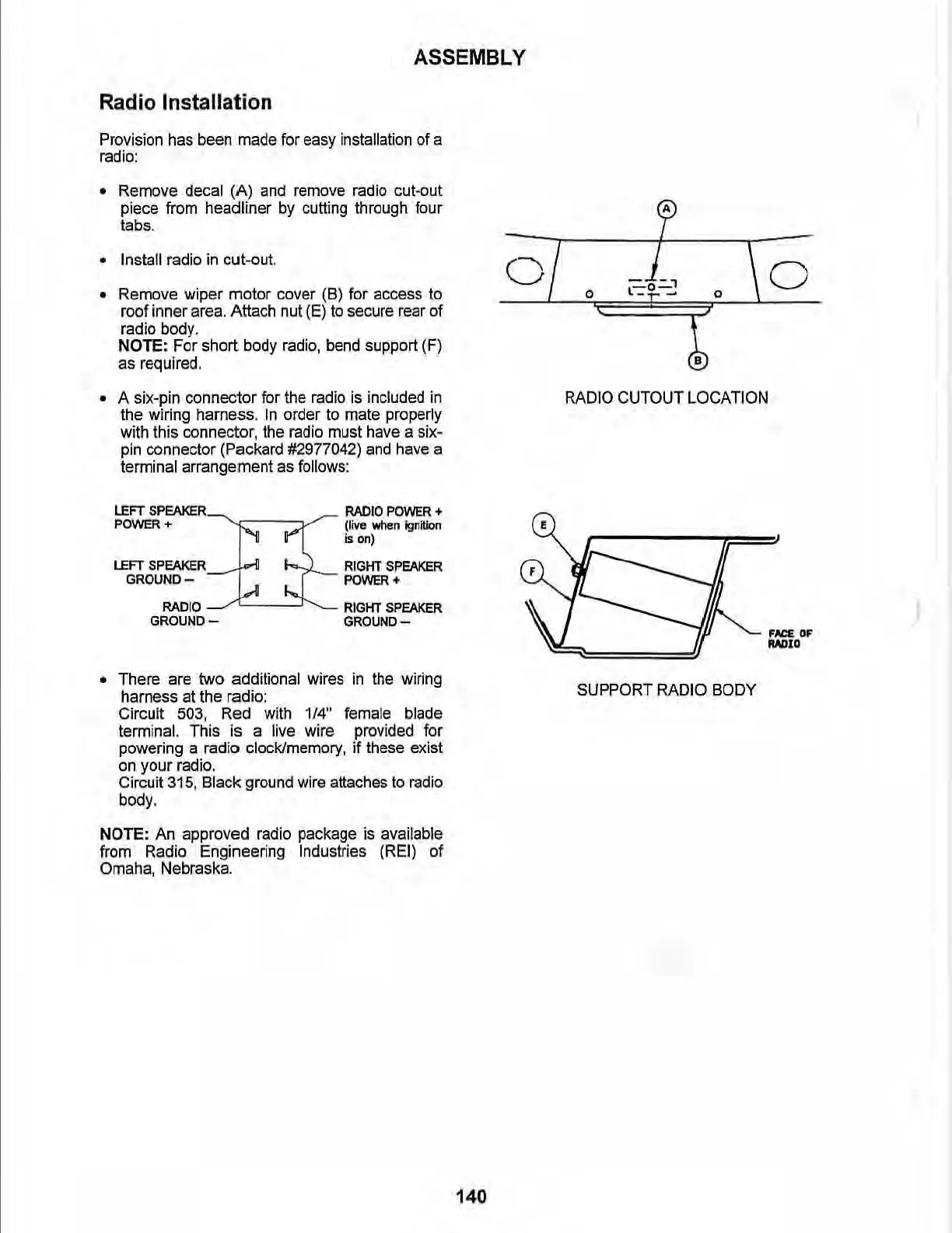
• Remove decal (A)
and
remove radio cut-out
piece from headliner
by
cutti
ng
through four
tabs.
• Install radio
in
cut-out.
• Remove wiper motor c
ov
er (6) for access
to
roof inner
area.
Attach
nu
t
(E)
to
secure
rear
of
radio
body
.
NOTE: For short body radio, bend support (F)
as
required.
• A six-pin connector for the radio
is
included in
the wiring harness.
In
order
to
mate properly
wi
th
this connector,
th
e radio must have a six-
pin
co
nnecto
r
(Packard
#2
977042)
and
have
a
terminal arrangement
as
follows:
LEFT
SPEAKER
RADIO
POWER
+
POV\IER
+
(live
when
ignition
is
on)
LEFT
SPEAKER
RIGHT
SPEAKER
GROUNO-
POWER+
RADIO
RIGHT SPEAKER
GROUND-
GROUND-
• There are two additional wires
in
the wiring
harness at the radio:
Circuit 503, Red wi
th
1/4"
female blade
terminal. This is a live wire provided for
powering a radio clock/memory, if these exist
on
your radio.
Circuit 315, Black ground wire attaches
to
radio
body_
NOTE: An approved radio package
is
available
from Radio Engineering Industries
(REI
) of
Omaha, Nebraska.
0
E
140
~
0
l=--t'="'l
-,-
-
0
RADIO CUTOUT LOCATION
SUPPORT RADIO BODY
o
FN:E.
OF
"',>I,