MAINTENANCE/SERVICE
Traction Drive: Neutral Lock and
Steering Checks (continued)
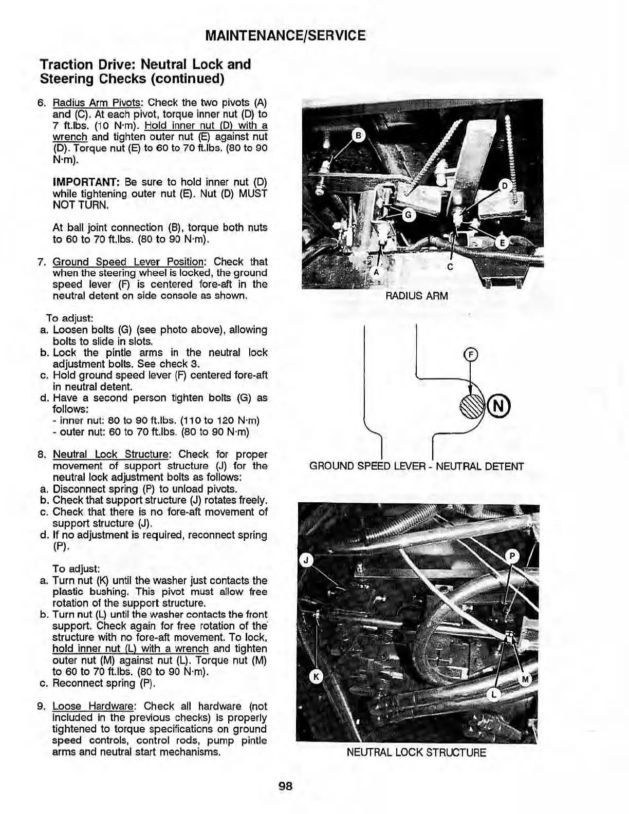
6.
Radius Arm Pivots:
Check
the two pivots
(A)
and (C). At each pivot, torque Inner nut
(D)
to
7 ft.lbs. (10 N·m).
Hold
inner nut
(0)
with a
wrench and tighten outer nut
(E)
against nut
(0). Torque nut
(E)
to
60
to 70 tUbs. (80 to 90
N'
m),
IMPORTANT:
Be
sure to hold inner nut (0)
while tightening outer nut
(E).
Nut (0) MUST
NOT
TURN
,
At ball joint connection (8). torque both nuts
to
60
to
70
ft.lbs. (80
to
90 N·m).
7. Ground Speed Lever Position: Check that
when the steering wheel
is
locked, the ground
speed
lever
(F)
is centered fore-aft in the
neutral detent on side console
as
shown.
To
adjust
a.
Loosen bolts
(G)
(see photo above), allowing
bolts to slide
in
slots.
b.
Lock
the
pintle arms
in
the
neutral lock
adjustment bolts.
See
check 3.
c.
Hold ground speed lever
(F)
centered fore·a
ft
in
neutral detent.
d.
Have a second person tighten bolts
(G)
as
follows:
•
inner nut:
80
to
90
fUb
s.
(110
to
120
N·m)
• outer nut:
60
to
70
ft.lbs.
(80
to
90
N·
m)
8. Neutral Lock Structure: Check for proper
movement of support structure
(J)
for the
neutral lock adjustment bolts
as
follows:
a.
Disconnect spring
(P)
to unload pivots.
b.
Check that support structure
(J)
rotates freely.
c. Check that there
is
no fore
-a
ft movement of
support structure
(J).
d. If no adjustment
is
required, reconnect spring
(P),
To adjust:
a.
Turn nut
(K)
until the washer just contacts the
plastic bushing. This pivot must allow free
rotation of the support structure.
b.
Turn nut
(L)
until the washer contacts the front
support.
Check again for free rotation of
the"
structure with
no
fore-
aft
movement.
To
lock,
hold
inner nut ILl with a wrench
and
tighten
outer nut
(M)
against nut
(L)
. Torque
nut
(M)
to
60
to
70
ft.lbs.
(80
to
90
N·
m).
c.
Reconnect spring
(P).
9.
Lo
ose
Hardwa
re
: Check
all
hardwa
re
(not
included
in
the previous checks)
is
properly
tightened to torque specifications
on
ground
speed
controls, control rod
s,
pump pintle
arms
and
neutral start
me
c
hani
s
ms
.
RADIUS
ARM
®
GROUND
SPEED
LEVER
-
NEUTRAL
DETENT
NEUTRAL
LOCK
STRUCTURE
98