ASSEMBLY/SETUP IN STRUC TIONS
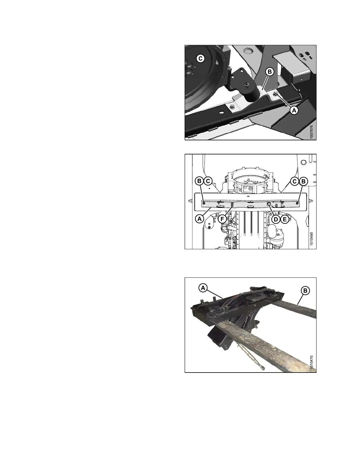
3. Remove the outer bolt and nut (A) from the front engine
mounts (B) on the left and right sides of the engine (C).
Retain nuts for reuse.
Figure 2.18: Front Engine Mounts
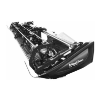
4. Mount the linkage support (A) to the windrower frame
with two 1/2 in. x 2-3/4 in. long hex head bolts (B)
with flat washers under the bolt heads and secure with
nuts (C).
NOTE:
These bol
ts replace the engine mount bolts removed
in Step 3.
, page 20.
5. From below the support, install a 3/4 in. x 3-1/2 in. long
hex head bolt (D) with a flatwasher under the bolt head.
6. Secure with a flat washer, a lock washer, and a nut on
topsideoftheframe.
7. From above the support, install a 3/4 in. x 5-1/2 in. long
hex head bolt (F) with a flat washer under the bolt head.
Do NOT install nut on bolt (F).
Figure 2.19: Linkage Support
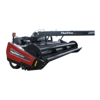
8. Support linkage assem bly (A) with a forklift.
NOTE:
Make s ure the
forks (B) do not lift against the
cylinder fitt
ing.
Figure 2.2
0: DWA Linkage
214049 20 Revision A


 To Next Page