ASSEMBLY/SETUP IN STRUC TIONS
9. Position the deck pivot (A) into the linkage clevis (B).
NOTE:
Make sure ther
e is a loose bushing inside the
deck pivot (A)
.
10. Align the de c
k p ivo t (A) with the holes in the clev is (B)
by raising or
lowering the floor jack, and insert shaft (C).
11. Install a reg
ular hex nut (D) to the bottom of the deck
pivot shaft
and torque the nut to 339 N·m (250 ft·lbf).
12. Insta ll a lo
ck nut (E), and tighten against nut (D).
IMPORTANT:
Apply proper torque to nuts.
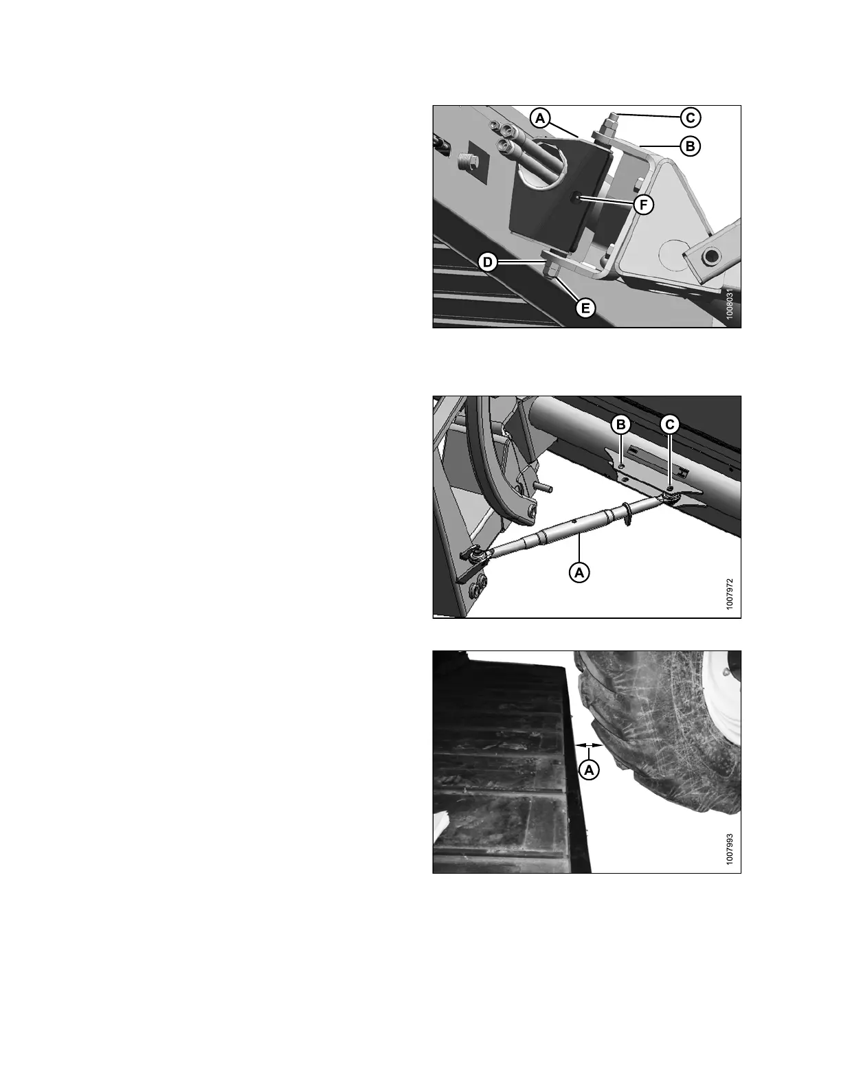
13. Add grease to grease zerk (F).
Figure 2.52: Deck Pivot
14. Attach turnbuckle (A) from linkage to deck.
• If used with an R-Series Rotary Disc Header, use
the inner pivot (B)
• IfusedwithanA-SeriesAugerorD-SeriesDraper
Header, use the outer pivot (C)
NOTE:
The turnbuckle length should b e approximately:
• 530 mm (21 in.) long for an R-Series Rotary
Disc Header
• 630 mm (25 in.) long for an A-Series Auger
Header or D-Series Draper Header
Figure 2.53: A
djustable Turnbuckle
15. Adjust the turnbuckle length so the space (A) between
the deck and the right-hand drive tire is approximately
100mm(4in.).
NOTE:
The single- a
cting lift cylinder is pressurize d w ith
the draper d
rive circuit. Therefore, when the
deck is set u
p for the rotary disc headers, the
windrower n
eeds to be running for the deck to
be in its mos
t forward position. This adjustment
can be fine-t
uned wh en the hydraulics setup is
complete.
Figure 2.5
4: Deck and RH Drive Wheel
214049 32 Revision A
 Loading...


