MAINTENANCE AND SERVICE
Form 169469/169470/169471 184 Revision C
7.11.5 HEADER AND REEL HYDRAULICS
7.11.5.1 Relief Valves
The pressure relief valves are pre-set for all
header sizes and options. See table below.
When the system operating pressure reaches
the relief valve setting, the relief valve opens
which causes a high pitch sound. Reduce the
ground speed to maintain the correct system
load and header drive operation.
An optional load sensor may be installed to warn
the operator that the system pressure is
approaching an overload condition, by a tone
and flashing the pressure reading. The load will
continue to rise if the operator does not reduce
ground speed and the relief valve opens at the
relief valve setting. See table below for
recommended settings.
If lift and drive capacity problems develop, the
pressure relief valve may require adjusting.
Contact your Windrower Dealer or refer to the
Technical Service Manual for your Windrower.
HEADER MODEL APPLICATION/SYSTEM
SUGGESTED OVERLOAD
WARNING SETTING
psi (kPa)
WINDROWER DIFFERENTIAL
RELIEF SETTING
psi (kPa)
R80/R85 Disc Pressure 5000 (34474) 5800 (39990)
D60 & A40D Reel/Draper Pressure 3000 (20684) 3500 (24132)
D60 & A40D Knife/Conditioner Pressure 4000 (27579) 4500 (31026)
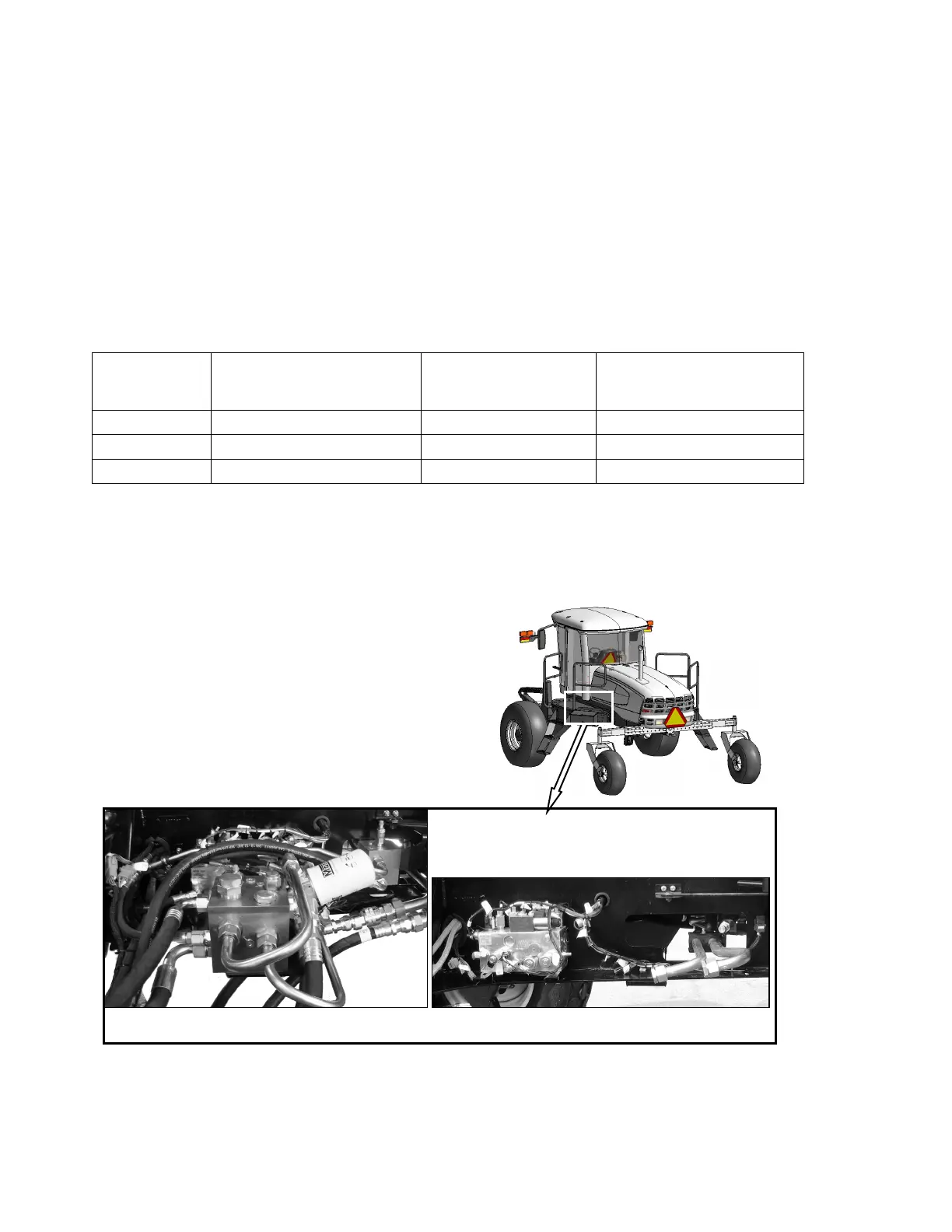
7.11.5.2 Flow Control Block
Two hydraulic valve blocks with multiple
cartridges are used for the various windrower
functions and are controlled by the Windrower
Control Module (WCM) according to the inputs
from the operator. The valve blocks are located
behind the left cab-forward side platform.
The valve blocks do not require any scheduled
maintenance other than to check for leaking
fittings or loose electrical connections. If service
is required, contact your Windrower Dealer or
refer to the Technical Service Manual for your
Windrower.
ROTARY DISC HEADER HYDRAULICS