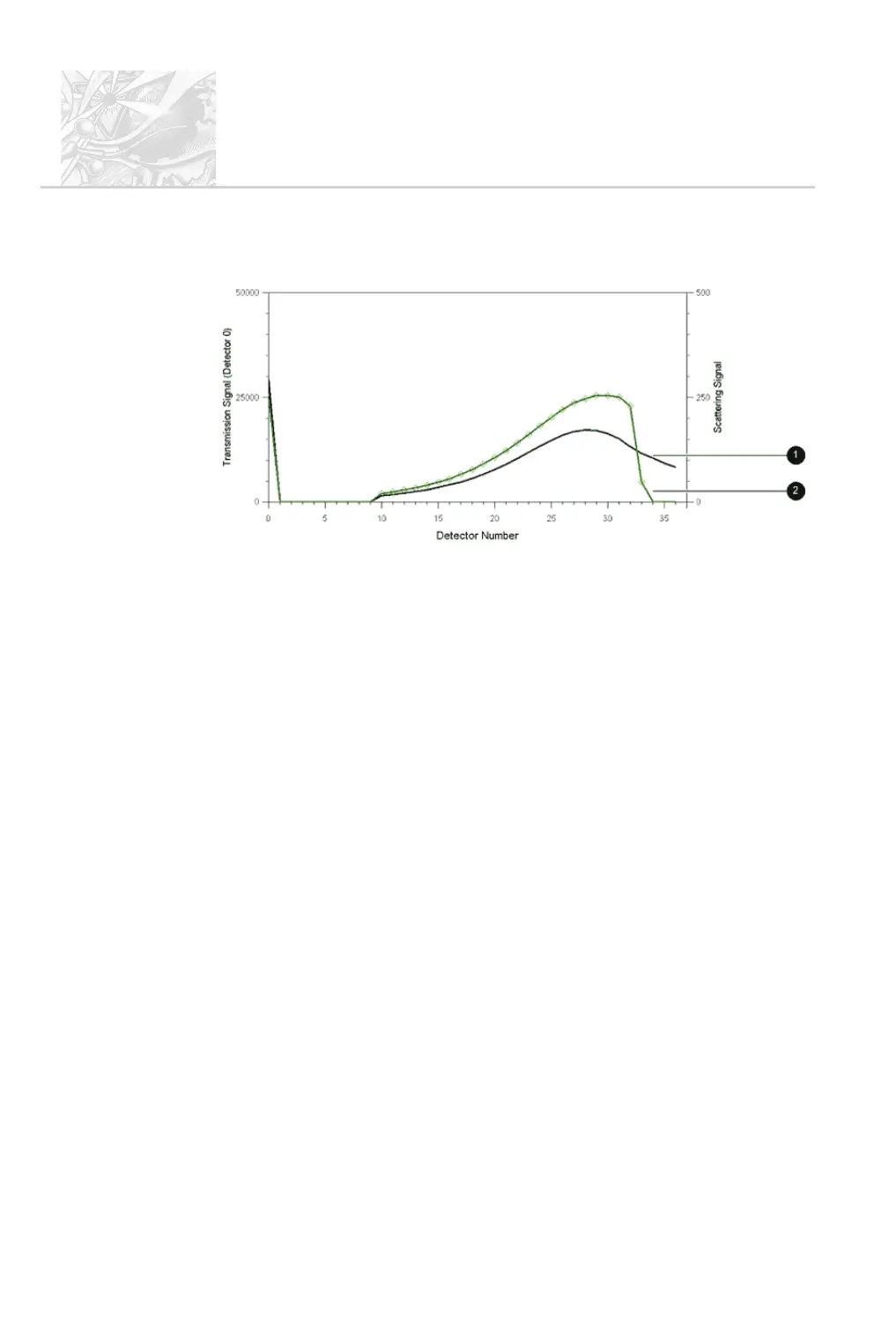
The diagram below shows the scattering data associated with the size distributions
shown above:
Curve
+
shows the measurement made within the working range. Curve
,
shows the measurement made outside of the working range. Here the lack of data
on the last five detectors is obvious. This is caused by vignetting.
There are two ways to stop vignetting:
.
Move the spray source towards the Receiver lens to a point where the re-
ported result does not vary with distance. This should be within the quoted
working range for the lens.
.
Use the Detector Range options to eliminate the detector channels af-
fected by vignetting. This reduces the resolution of the analysis in the
sub-micron size range, so should only be done if it is not possible to posi
-
tion the spray closer to the Receiver.
In the above example, the effect of vignetting can be overcome by
eliminating the last five detector channels from the analysis.
Beam steering
Beam steering occurs when a significant volume of propellant gas or another
gaseous phase apart from air is present in the measurement zone. When the
Spraytec is set up, the system is aligned with air present in the measurement zone.
Gases such as propellants have a refractive index significantly different from air.
This causes the laser beam to become unfocussed, leading to a high scattering
signal on the first set of detector channels. Although this signal is not caused by
CHAPTER 6
Spraytec
Page 6.20 MAN 0368
ILL 7457