'
Note
.
The electrical background measurement includes any signal caused
by ambient light in the room. Ensure no bright lights shine directly into
the Spraytec optics. Do not work next to a window where sunlight can
interfere with the measurement as this may cause the overall ambient
light levels to change during the measurement.
In addition to the detectors shown above there is one extinction detector channel
which measures unscattered light from the Transmitter, giving 34 and 37 data
channels for the 750mm and 300mm lenses respectively.
The Receiver has a status indicator on the front. This is illuminated when the
instrument is fully powered on.
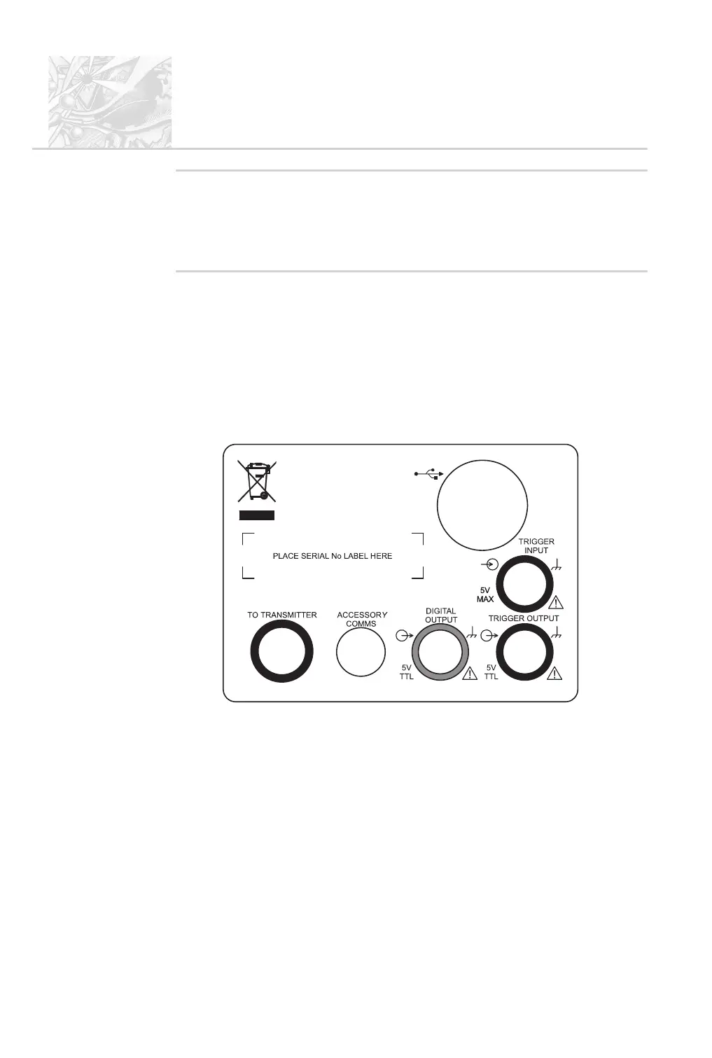
Connections
The connections on the back of the Receiver are labelled as shown below:
These are used as follows:
.
USB – the large shielded end of the USB cable plugs into this socket, con
-
necting to the USB port on the back of the PC.
.
TO TRANSMITTER – a LEMO cable with blue connectors is connected
from here to the socket in the Receiver end of the X-bar. This connects to
the Transmitter through the centre of the X-bar.
.
DIGITAL OUTPUT – this 5V TTL output is used to drive an extractor
unit or a mains-powered device (via the switching box). The Spraytec Ac
-
cessories User Manual gives details on connecting the extractor unit.
CHAPTER 3
Spraytec
Page 3.6 MAN 0368
ILL 7426