ENGINE AND ENGINE SYSTEMS CD3340B/YB4411
6-12
Published 04/07/2015 Control # 569-00
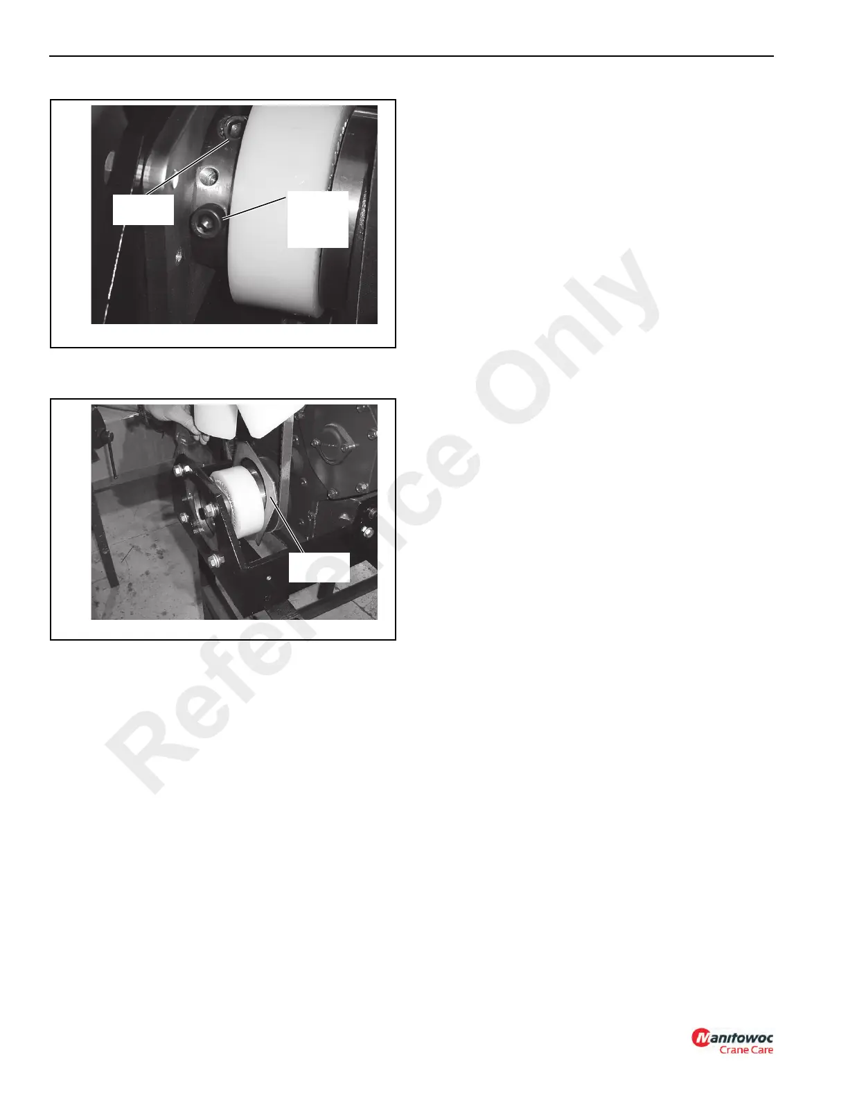
11. Insert the installation shim (Figure 6-3) behind coupling
sleeve (4, Figure 6-4) as shown in Figure 6-14.
12. Install pump (1, Figure 6-4) as shown. Apply Loctite®
243 to the threads of capscrews (21, Figure 6-4). Attach
the pump with capscrews (21), lockwashers (22), and
flat washers (23). Tighten the capscrews to a torque of
87 Nm (64 lb-ft).
13. Push pump coupling hub (5, Figure 6-4) towards the
engine with socket head capscrews (13) against
coupling sleeve (4), the sleeve against the shim, and the
shim against drive coupling (2). Tighten clamping bolt
(16, Figure 6-4). Tighten the bolt to a torque of 86 Nm
(63 lb-ft). Remove the installation shim.
14. Attach all hoses to the hydraulic pump.
15. Lower the engine and install the front mounting
hardware (15 and 11, Figure 6-4).
16. Remove the lifting chain.
17. Install the alternator and connect the wires to the
alternator and engine bracket.
18. Fill the hydraulic oil reservoir.
NOTE: The hydraulic system requires clean hydraulic oil
for proper operation. Contaminated oil can cause
damage to the pump and other components.
Before adding any hydraulic oil to the hydraulic
system, be sure the oil is filtered through a 10-
micron (absolute) or less filter.
19. Connect the battery cables.
20. Start the engine and let it idle. Check for hydraulic leaks
around the pump. Tighten any loose fittings, clamps, and
hoses if loose.
21. Install the rear tires and raise the outriggers.
22. Tighten the wheel lug nuts to a torque of 408 Nm (300 lb-
ft).
FIGURE 6-13
p1419
Clamping
Bolt
Socket
Head
Capscrew
No. 13
FIGURE 6-14
p1420
Shim
(1007422)
Reference Only

 Loading...


