GROVE 7-35
CD3340B/YB4411 TRANSMISSION AND TORQUE CONVERTER
Published 04/07/2015 Control # 569-00
Component Identification for Figure 7-30
Figure 7-30 shows all the components which are referred to in the disassembly/assembly procedures. Item numbers
correspond with numbers in the instructions and the following illustrations.
11. Remove and discard pump sealing ring (16).
12. Separate the pump components.
13. Remove and discard oil seal (17) from the pump
housing.
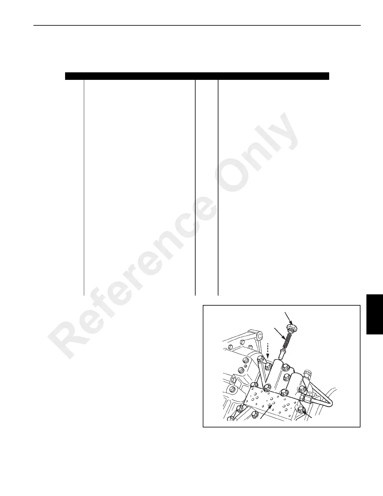
14. Unscrew plug (18, Figure 7-31) and remove the
pressure maintenance valve spool and spring (19).
15. Unscrew fourteen bolts (20) and remove solenoid
adapter block (21).
16. Remove and discard gasket (52).
Item Description Item Description
1 Bolt 31 Case Mounting Bolts
2 Oil Strainer 32 Transmission Rear Case (Output end)
3 Gasket 33 O-ring (3)
4 Drain plug 34 Shim(s)
5 Oil Filter 35 Case Mounting Bolts (11)
6 Oil Pressure Switch 36 Flywheel Housing
7 Speed Sensor 37 Dowels(2)
8 Sealing Caps (6) 38 Brake Disc
9 Capscrew (6) 39 Output Shaft Washer
10 Solenoid Control Valve (Forward High/Low 40 Output Shaft Nut
11 Solenoid Control Valve (Mainshaft/Layshaft) 41 Output Shaft
12 Solenoid Control Valve (Reverse High/Low) 42 Oil Seal
13 O-rings (12) 43 Outer Taper Roller Bearing
14 Transmission Pump Mounting Screws (4) 44 Spacer
15 Transmission Pump Assembly 45 Inner Taper Roller Bearing
16 Pump Sealing Ring 46 Piston Ring Seals
17 Pump Housing Oil Seal 47 Forward Shaft Sealing Plug
18 Plug 48 Sealing Washer
19 Pressure Maintenance Valve 49 Transmission Front Case (Input End)
20 Bolt (14) 50 Spacer
21 Solenoid Adapter Block 51 O-ring (2)
22 Screw (3) 52 Adapter Block Gasket
23 Baffle Plate 53 Brake Mounting Plate
24 Gasket 54 Taper Roller Bearing (8)
25 Torque Converter Relief Valve 55 Spacer
26 Cover Bolts (4) 56 Copper Washer
27 Layshaft End Cap P Forward Clutch Assembly
28 Gasket Q Mainshaft Clutch Assembly
29 Shim(s) T Layshaft Clutch Assembly
30 O-ring Y Input Clutch Assembly
FIGURE 7-31
A0807
18
19
52
21
20
Reference Only
 Loading...


