TRANSMISSION AND TORQUE CONVERTER CD3340B/YB4411
7-36
Published 04/07/2015 Control # 569-00
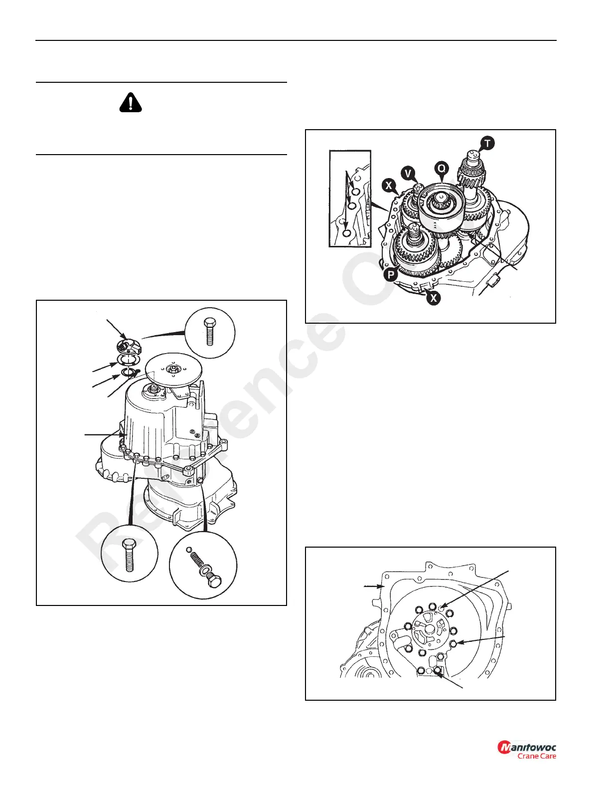
17. Position the transmission vertically, standing on the face
of the flywheel housing as shown in Figure 7-32.
18. Remove torque converter relief valve ball, tapered
spring and sealing washer (25).
19. Remove four bolts (26) and remove layshaft end cap
(27). Discard sealing gasket (28).
20. Remove layshaft shim (29) and O-ring (30).
21. Unscrew nineteen bolts (31) and lift off rear end casing
(32).
NOTE: Sealant holds the two casings together, carefully
tap the casings while prying the casings apart at
locations X in Figure 7-33. DO NOT pry open
between the casings or the sealing faces will be
damaged.
NOTE: Make sure that the internal components, except
spined output shaft and brake disc, remain seated
in the front casing. If necessary, rotate the brake
disc back and forth slightly to dislodge the internal
components.
22. Remove and discard three O-rings (33, Figure 7-33).
23. Tilt and lift out layshaft assembly (T).
NOTE: For reference, the clutch assemblies are identified
as follows.
P = Forward Clutch Q = Mainshaft
T = Layshaft V = Input Clutch
24. This step requires the help of an assistant. Have the
assistant SLIGHTLY lift and tilt both the main shaft (Q)
and input clutches (V) as shown in Figure 7-33; then tilt
and lift out the forward clutch (P).
25. Slightly lift input clutch (V) and at the same time tilt and
lift out main shaft (Q).
26. Lift out input clutch (V).
NOTE: Retrieve shims (34) from casing for reuse.
Disassembly and assembly procedures for the
shaft and clutch assemblies are given elsewhere in
this section.
CAUTION
The transmission weighs approximately 220kg (484 lb)
dry. Use adequate hoist and chains. Personal injury could
occur from improperly supported transmission.
FIGURE 7-32
a0808
26
27
28
29
30
32
31
25
Reference Only
 Loading...


