GROVE 7-37
CD3340B/YB4411 TRANSMISSION AND TORQUE CONVERTER
Published 04/07/2015 Control # 569-00
27. Unscrew eleven bolts (35, Figure 7-34) and remove
flywheel housing (36). It may be necessary to tap the
housing with a soft hammer to release the flywheel from
dowels (37).
28. Mark the position of the brake disc (38, Figure 7-35) on
the spline output shaft (41). While holding the disc,
unscrew output shaft nut (40) and remove with washer
(39). Support output shaft (41) from beneath and lift off
the brake disc. Remove the output shaft assembly.
NOTE: Due to ratio options some transmissions feature a
larger output gear (Z). When removing the output
shaft (41) the gear may hit the gearbox housing,
preventing removal. For shaft removal procedures
see Output Shaft Removal - Larger Diameter Gear.
29. Pry out oil seal (42) and discard.
30. Remove outer taper bearing (43).
31. Remove spacer (44) and retain for assembly, if type Y.
NOTE: If spacer (44) is the collapsible type (X,
Figure 7-35), discard it. It is recommended
replacing it with a solid spacer. See Assembly step.
32. Using a suitable puller, remove inner bearing (45).
33. Remove and discard two O-rings (51, Figure 7-36) from
casing (49).
34. Carefully, from inside casing (49), tap out spacer (50).
35. Finally, after disassembly, make sure casings and parts
have been thoroughly cleaned using suitable solvents
before starting the assembly procedures. Be sure the
suction strainer is thoroughly cleaned and dried before
assembly.
Assembly
NOTE: Before starting the assembly of the transmission,
make sure that all casings and components,
including the suction strainer, have been
thoroughly cleaned with a suitable solvent.
When assembling, coat bearings with a Lithium Base, E.P.
No. 2 bearing grease. Replace all O-rings, seals and
gaskets.
Remember that dirt in the transmission system will cause
damage to the transmission and its associated parts,
particularly the transmission pump.
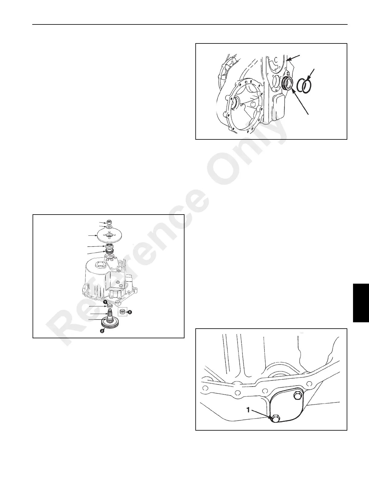
1. Using a new gasket, install the suction strainer. Apply
Loctite 243 to bolts (1, Figure 7-37) and tighten to a
torque of 10 Nm (7 lb-ft).
If removed, install bearing cups into gear casing.
NOTE: If the transmission has not been thoroughly
cleaned during overhaul, any particles below 200
microns (0.2 mm) can pass through the existing
suction strainer and into the transmission pump
before being caught in the pressure filter.
It is recommended that a special 75 micron (0.075
mm) service suction filter be temporarily installed.
FIGURE 7-35
a0811
40
39
38
42
43
45
41
44
Reference Only
 Loading...


