TRANSMISSION AND TORQUE CONVERTER CD3340B/YB4411
7-38
Published 04/07/2015 Control # 569-00
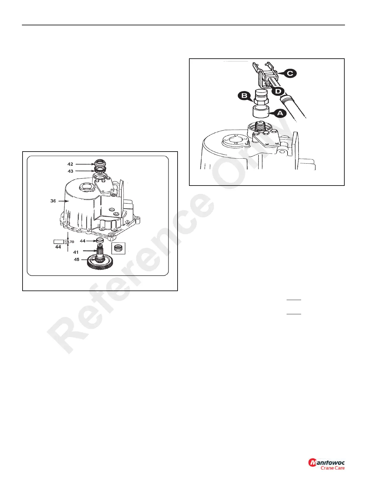
2. Lightly oil output shaft inner bearing (45, Figure 7-38)
and cup and install to output shaft 41.
NOTE: The transmission should be rebuilt with a solid
spacer 44, which is the preferred option. However,
in the absence of the special tools required or of a
solid spacer, a collapsible spacer may be installed.
See Figure 7-20 for Setting Tool Kit.
a. Install the solid spacer 44 (13.70 mm thick, P/N
1902707) over output shaft 41 and assemble into
casing 36.
b. Lightly oil output shaft outer bearing 43 and cup and
install to output shaft 41, do not install oil seal 42 at
this time.
3. Install special tool sleeve (A, Figure 7-43), which
temporarily replaces the output flange, and secure with
special tool nut B, tighten to a torque of approximately
50 Nm (37 lb-ft). For special tool, see Figure 7-20.
NOTE: Check for end play while tightening nut B, if there is
no end play check the following:
a. The bearing cups are pushed fully into the casing.
b. The correct bearings are installed.
c. The solid spacer (44, Figure 7-38) is 13.70 mm
thick.
d. Install special tool pillar C so that the fork end
engages in special tool nut B, tighten bolt D.
4.
a. Install dial test indicator (E, Figure 7-43).
b. Set torque wrench to 35 Nm (27 lb-ft) and measure
the end play while rotating the output shaft.
c. To select the right size spacer 44, Figure 7-38
subtract the end play obtained at step B from the
solid spacer 44 (13.70 mm). Also, subtract 0.120
mm to allow for bearing tolerances and pre-load. If
there is no spacer of this size, install the next
smallest spacer.
If the “Result” measurement is outside the spacer kit range,
check the assembly of the bearings. If the bearings are
assembled correctly, use a collapsible spacer. See
installation procedure.
Example:
Service spacer
Subtract end play
=
Subtract tolerance & pre-load
Results
Use next smallest spacer i.e.
13.70
00.41
13.29
00.12
13.17
13.15
Reference Only
 Loading...


