GROVE 7-47
CD3340B/YB4411 TRANSMISSION AND TORQUE CONVERTER
Published 04/07/2015 Control # 569-00
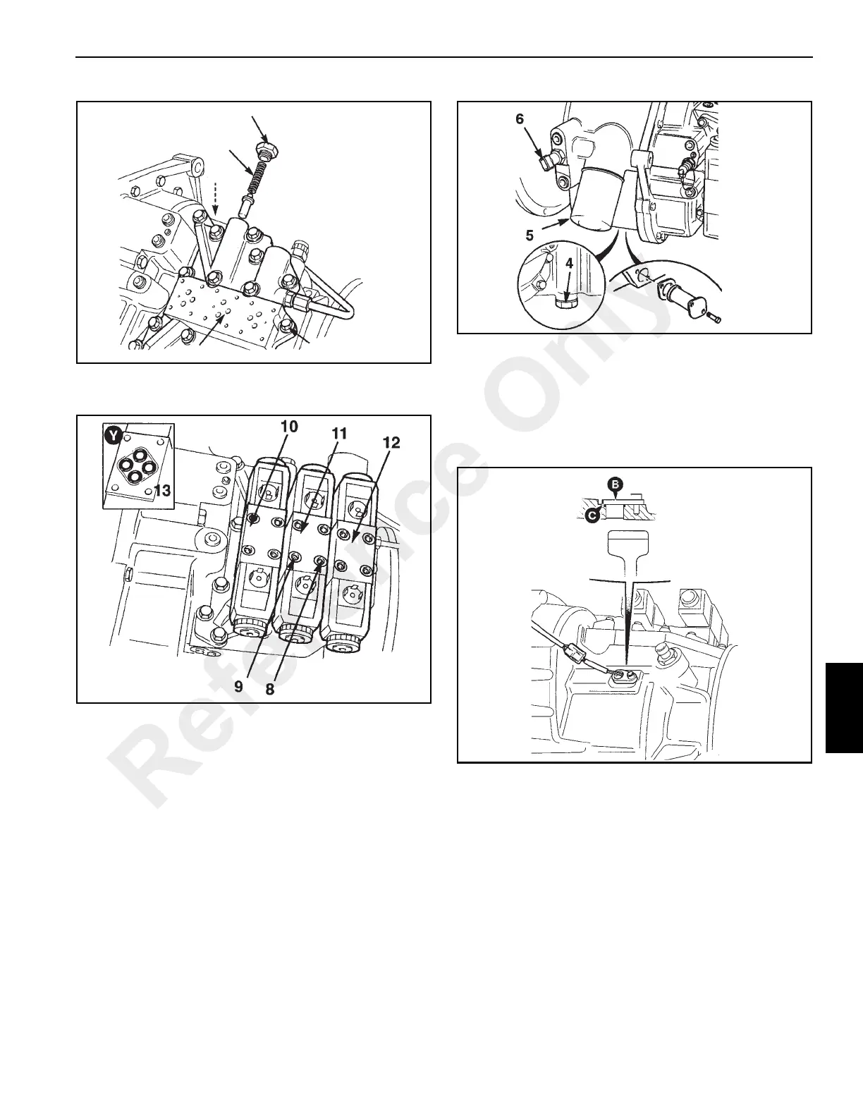
33. Install new O-rings (13, Figure 7-63) into each valve
body.
34. Position the reverse high/low clutch solenoid (12) onto
the adapter block. Install capscrews (9) and tighten to a
torque of 5 Nm (4 lb-ft).
35. Repeat step 34 for the main shaft/layshaft clutch
solenoid (11) and for the forward clutch solenoid (10).
NOTE: The mounting holes will only align when the
solenoid valve has been positioned correctly on the
adapter block.
36. After assembly, insert the plastic caps (8) into the
mounting screw counter-bores to inhibit water and dirt
entry which could inhibit removal at a later date.
37. Coat the seal of a new filter (5, Figure 7-64) with
transmission oil. Screw the filter on until it just contacts
the filter head. Turn the filter at least another 3/4 turn.
38. Install the drain plug (4) with a new sealing washer.
Tighten to a torque of 203 Nm (150 lb-ft).
39. Install pressure switch (6) with a new sealing washer.
Tighten to a torque of 28 Nm (21 lb-ft).
40. Install the electronic speed sensor (B, Figure 7-65). Use
a new O-ring (C).
Installation
1. Install the torque converter.
2. Clean and lubricate the splines of the transmission input
shaft on the engine.
3. Align the transmission input shaft splines with the
splines of the torque converter impeller and assemble
the transmission/torque converter housing to the engine
flywheel housing. Install the 12 bolts and lockwashers
and tighten to proper torque. See Fasteners and Torque
Values, page 1-8.
4. Install the power unit into the machine. See Engine and
Engine Systems, page 6-1.
FIGURE 7-62
a0807
20
21
18
52
19
Reference Only
 Loading...


