GROVE 8-5
CD3340B/YB4411 AXLES/DRIVE SHAFTS/WHEELS AND TIRES
Published 04/07/2015 Control # 569-00
4. If tow-in is incorrect, loosen the jam nuts (Figure 8-9)
securing the guide rods to the cylinder rod.
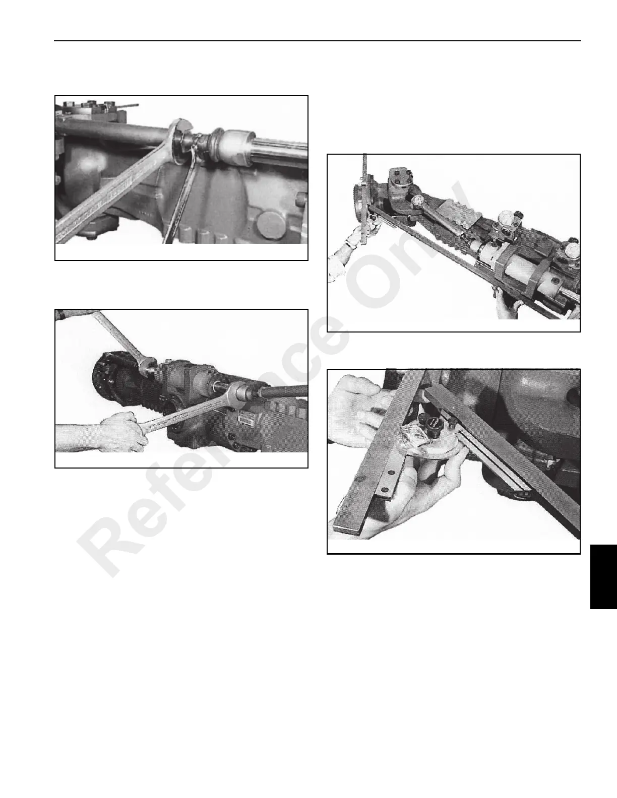
5. Using two wrenches on the guide rods (Figure 8-10),
screw in or out the two tie rods equally until both
dimensions are equal.
6. After the adjustment is correct, tighten the jam nuts
(Figure 8-9) against the guide rods.
Steering Angle Check and Adjustment
NOTE: Some of the following figures do not show the exact
axle used on your crane, but the procedure is the
same.
1. Use the same bars assembled for the toe-in adjustment,
page 8-5.
2. Steer the axle to maximum steering position.
3. Hold a long bar against the steering cylinder mounting
brackets on the axle (Figure 8-11), so that the two bars
form an acute angle.
4. Adjust a goniometer to 35° and position it on the long bar
(Figure 8-12).
5. Check the angle between the two bars. If not 35° adjust
the angle.
Reference Only
 Loading...


