AXLES/DRIVE SHAFTS/WHEELS AND TIRES CD3340B/YB4411
8-4
Published 04/07/2015 Control # 569-00
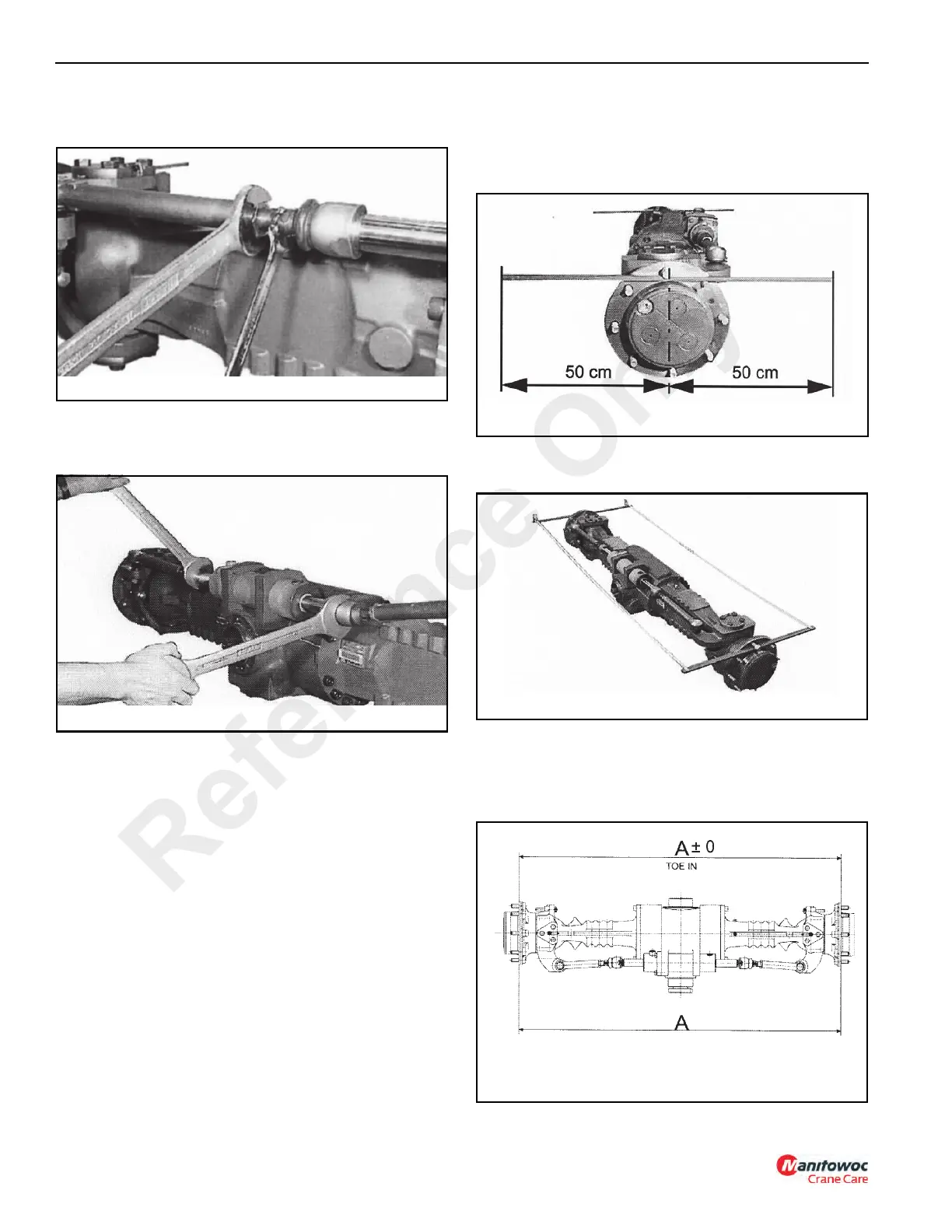
3. If toe-in is incorrect, loosen the jam nuts (Figure 8-4)
securing the guide rods to the cylinder rod.
4. Using two wrenches on the guide rods (Figure 8-5),
screw in or out the two tie rods equally until both
dimensions are equal.
5. After the adjustment is correct, tighten the jam nuts
(Figure 8-4) against the guide rods.
Checking with Axle Removed from Machine
1. Place two equal (one-meter) long linear bars on the
wheel sides of the hubs and lock them in place with two
nuts on the wheel stud bolt (Figure 8-6)
2. Measure the distance in millimeters between the bar
ends (both ends) with a tape line (Figure 8-7).
NOTE: Record the minimum value, swinging the
measurement point.
3. Check that there is no difference in the measurements
(Figure 8-8). Both measurements must be the same.
Reference Only
 Loading...


