GROVE 8-3
CD3340B/YB4411 AXLES/DRIVE SHAFTS/WHEELS AND TIRES
Published 04/07/2015 Control # 569-00
Toe-in.....................................................................0°
Steering Angle.....................................................35°
Bevel gear reduction..........................................1.55:1
Hub reduction.....................................................6.00:1
Total Reduction..................................................10.66:1
Bevel gear set backlash.........................0.15 - 0.20 mm
(0.006 - 0.008 in)
Pinion bearings (measured D=34.8 mm without seal).......P =
9.2 ÷ 13.8 daN
Total pinion ring gear bearing pull (measured D = 34.8 mm
without seal)...................................T = (P+3.85)˜(P+5.8) daN
Rear Steering Non-drive Axle
Installation...................................................Rigid pad mount
Weight..........................................................185 kg (408 lb)
Number of steering cylinders..........................Two
Brakes..........................................................None
Toe-In...........................................................0°
Toe-Out.........................................................0°
TOE-IN/STEERING ANGLE ALIGNMENT
Front Steering Axle
Toe-in Check and Adjustment
Checking with Axle on Machine
1. Place the wheels in the straight forward position.
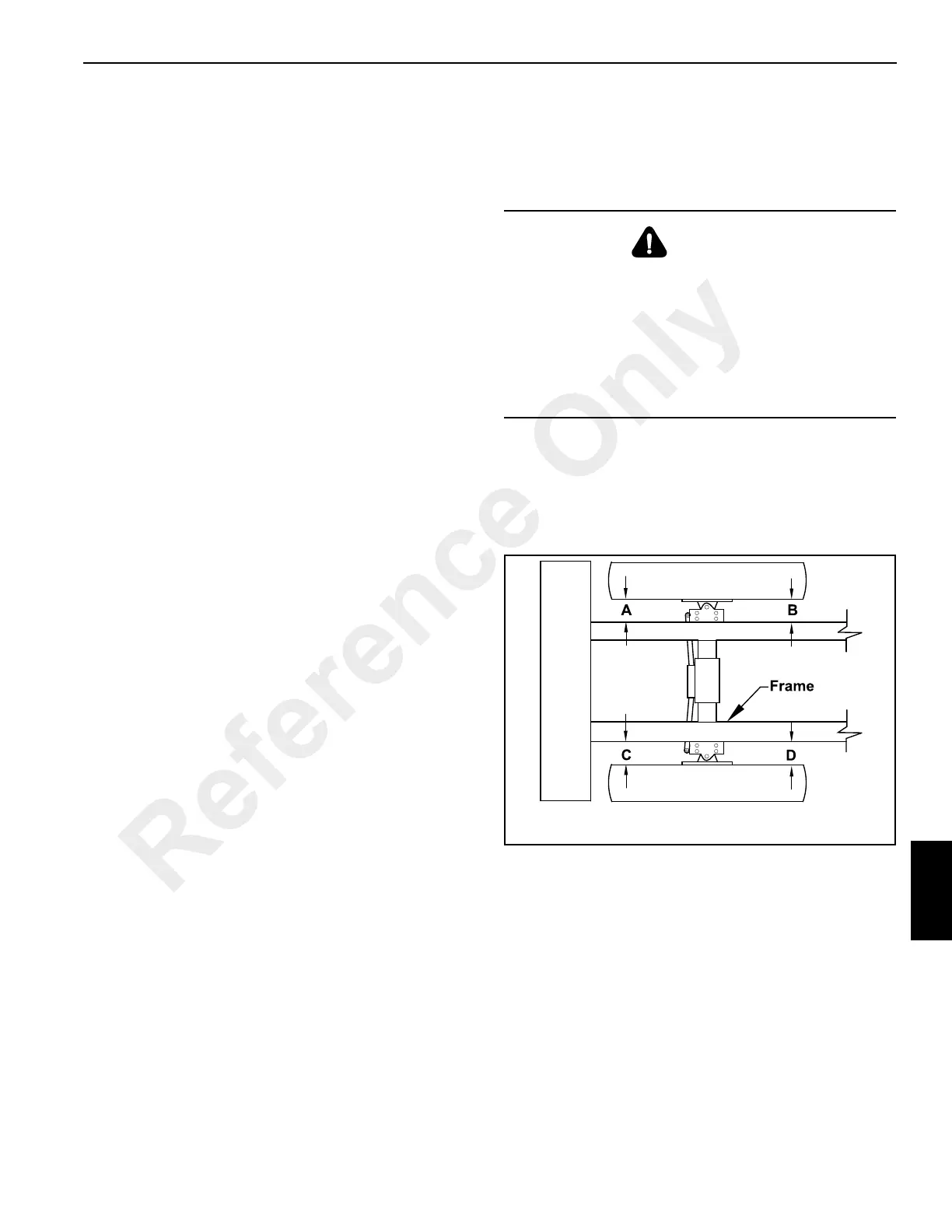
2. Take measurements from the tire to the crane frame at
the four positions A, B, C and D indicated in Figure 8-3.
All four dimensions must be equal.
WARNING
A raised and badly supported machine can fall on you
causing severe injury or death. Position the machine on a
firm, level surface before raising one end. Ensure that the
other end is securely chocked. Do not rely solely on the
machine’s hydraulics or jacks to support the machine
when working under it.
Disconnect the battery cables while you’re under the
machine to prevent the engine from being started.
Reference Only

 Loading...


