GROVE 8-19
CD3340B/YB4411 AXLES/DRIVE SHAFTS/WHEELS AND TIRES
Published 04/07/2015 Control # 569-00
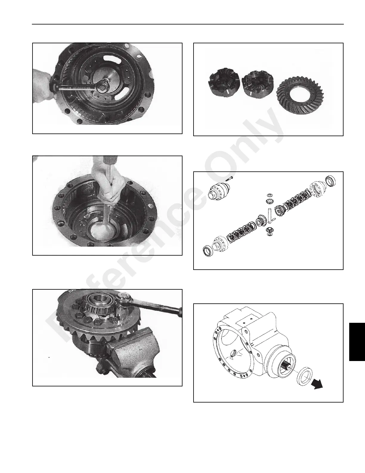
13. Using a hammer and driver, remove the bearing cup
from the brake flange (Figure 8-70).
Differential Disassembly
1. Place the differential in a vice with soft jaws. Remove the
bevel gear crown screws (Figure 8-71).
2. Mark the two differential housing halves to aid in
correctly positioning the housing halves during
assembly. Separate the two differential housing halves
(Figure 8-72).
3. Disassemble the components (Figure 8-73). Check for
proper operation and for any damage or wear to the
components. Remove the bearings from the differential
housing halves using a suitable puller.
Pinion Disassembly
1. Using a puller, remove the seal ring (Figure 8-74) from
the center housing. The seal ring will be damaged.
2. Position the center housing on a flat surface. Do not pry
the ring nut out of housing (Figure 8-75). Damage to the
bevel pinion threads will occur.
Reference Only
 Loading...


