EasyManuals Logo
Home>Manitowoc>Construction Equipment>Grove CD3340B

Manitowoc Grove CD3340B User Manual

Manitowoc Grove CD3340B
362 pages
To Next Page IconTo Next Page
To Previous Page IconTo Previous Page
Page #236 background imageLoading...
Page #236 background image
AXLES/DRIVE SHAFTS/WHEELS AND TIRES CD3340B/YB4411
8-20
Published 04/07/2015 Control # 569-00
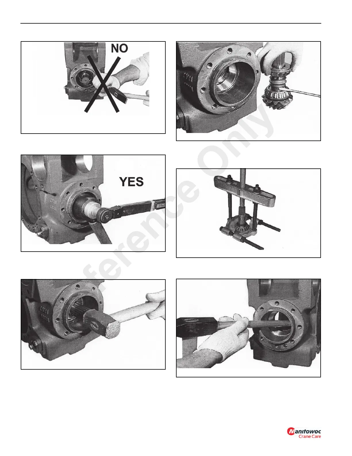
3. Remove the ring nut (Figure 8-76) with SPECIAL
TOOLS P/N 1901768.
4. Using a soft hammer, strike the end of the splined end of
the pinion to remove the pinion assembly from the
housing (Figure 8-77).
5. Remove the washers, elastic spacer and bearing cones
from the pinion (Figure 8-78). The elastic spacer must
be replaced with a new one.
6. Using a suitable puller, remove the bearing cone from
the bevel pinion (Figure 8-79). Remove the adjusting
shim under the bearing and check for wear and damage.
7. Using a chisel and hammer, remove the taper roller
bearing cups from the center housing (Figure 8-80).
P0619
FIGURE 8-75
P0620
FIGURE 8-76
P0621
FIGURE 8-77
P0622
FIGURE 8-78
P0623
FIGURE 8-79
FIGURE 8-80
P0624
Reference Only

Table of Contents

Questions and Answers:

Question and Answer IconNeed help?

Do you have a question about the Manitowoc Grove CD3340B and is the answer not in the manual?

Manitowoc Grove CD3340B Specifications

General IconGeneral
BrandManitowoc
ModelGrove CD3340B
CategoryConstruction Equipment
LanguageEnglish

Related product manuals